HF Receiver Schwabenland (LN 21021)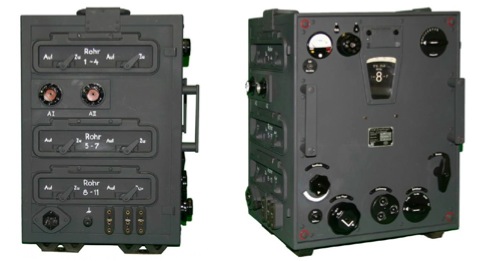
History
The short wave receiver Ln 21 021 "Schwabenland” was designed for Luftwaffe and used also by Kriegsmarine with the name EO8268. The receiver was developed by the Company C. Lorenz A.G. and produced in the years 1941-42. At that time, before the introduction of the receiver E52 Koln (mid 1942) was the best HF receiver available worldwide. Schwabenland was employ in fixed ground stations, vehicles, large ships and as part of the finding system Fu Peil A70b (KW-Adcock-Peilanlagen). Only a relatively small number was built: about 1000 devices.
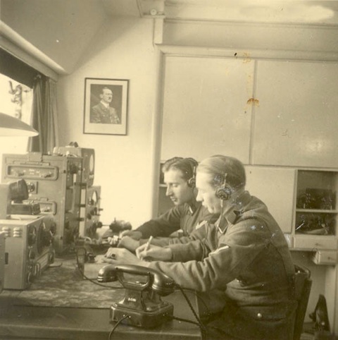
Picture taken during WWII shows Schwabenland in operation (battlefrequencies.com collection. Used with permission)
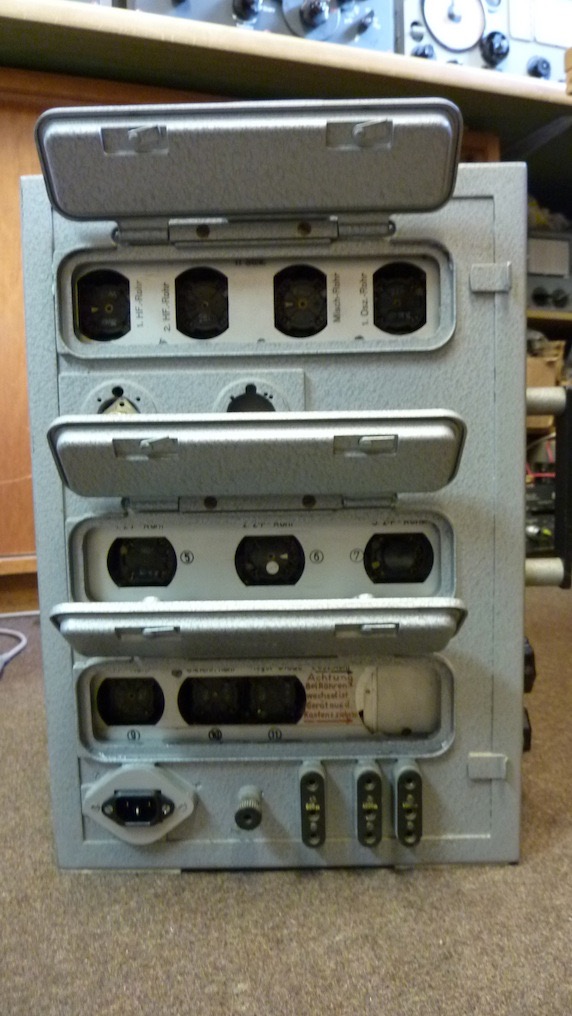
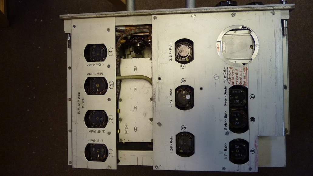
Schwabenland is, a single conversion receiver with two RF stage and an intermediate frequency of 1.24 MHz, designed for the reception of not modulated telegraphy (A1), modulated telegraphy (A2) and telephony (A3). The receiving frequency range is from 1,5 to 25 MHz subdivided into eight separate bands, each of which with a slightly overlap. To increase the selectivity is implemented a selectable crystal filter.
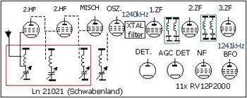
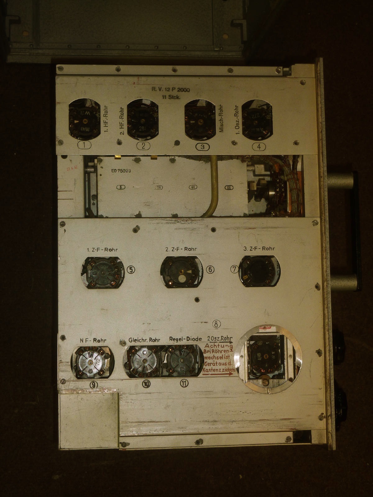
The second oscillator is crystal controlled. He makes audible not modulated CW and is also used as reference frequency generator. The radio is equipped by 11 valve RV12P2000, voltage stabilizer StV150/20 and TE30 as atmospheric protection for the antenna line.
The anode voltage is obtained by means of a selenium rectifier.
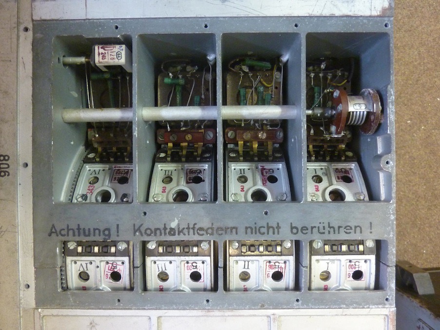
RF Amplifier, 1st Oscillator and mixer
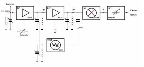
The reception frequency coverage is divided into eight bands. Switching between these is done by a mechanical drum and tuning is implemented buy four variable capacitors. There are three tuned RF circuits before that the signal is converted by mixed . The valve Rö11 implements the fist RF amplifier stage. The gain of this amplifier can be manually changed at the front panel. The gain of the second RF stage is controlled by the AGC control. Rö11 and local oscillator equipped by Rö71 implement the mixer stage. The output of the mixing valve Rö11 is connected at the crystal filter with continuously variable QF1 bandwidth.
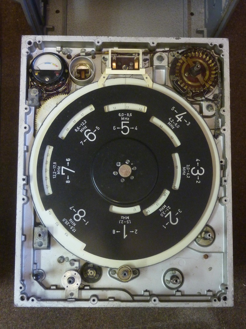
The frequency coverage, for each band, is the following:
Band 1 : 1500 - 2100 KHz
Band 2 : 2100 - 3000 KHz
Band 3 : 3000 – 4270 KHz
Band 4 : 4270 – 6100 KHz
Band 5 : 6100 – 8730 KHz
Band 6 : 8730 – 12500 KHz
Band 7 : 12400 – 17200 KHz
Band 8 : 17200 – 25000 KHz
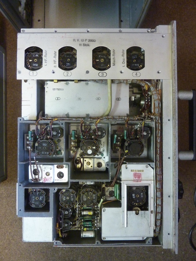
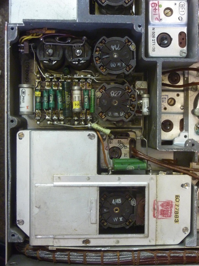
IF amplifier, demodulator and AGC
The receiver uses an intermediate frequency of 1,24 MHz At the input of the IF the amplifiers there’s the crystal filter QF1, whose 3-dB bandwidth are constantly changing through variation of the coupling B between 200 and 8000 Hz and has a high slew rate of its pass-band curve.
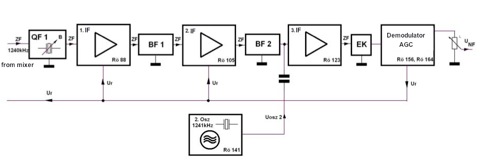
Quartz is filter followed by three IF stages. The first two are coupled band pass filters. At the output of the third IF stage is controlled by a a single circuit that implement AGC and the demodulator. The second quartz-controlled oscillator with a frequency of 1.241 MHz overlaid the not modulated CW signals and also works as a calibration oscillator.
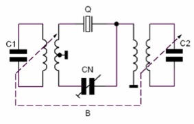
The Quartz filter is a differential bridge filter (phasing or Lattice filter). CN is the so-called phasing control. If this is set to a minimum value, the filter has a form which is an almost symmetrical band-pass shape. As CN is increased, a notch appears in the stop-band and progressively rises in frequency towards the pass-band peak
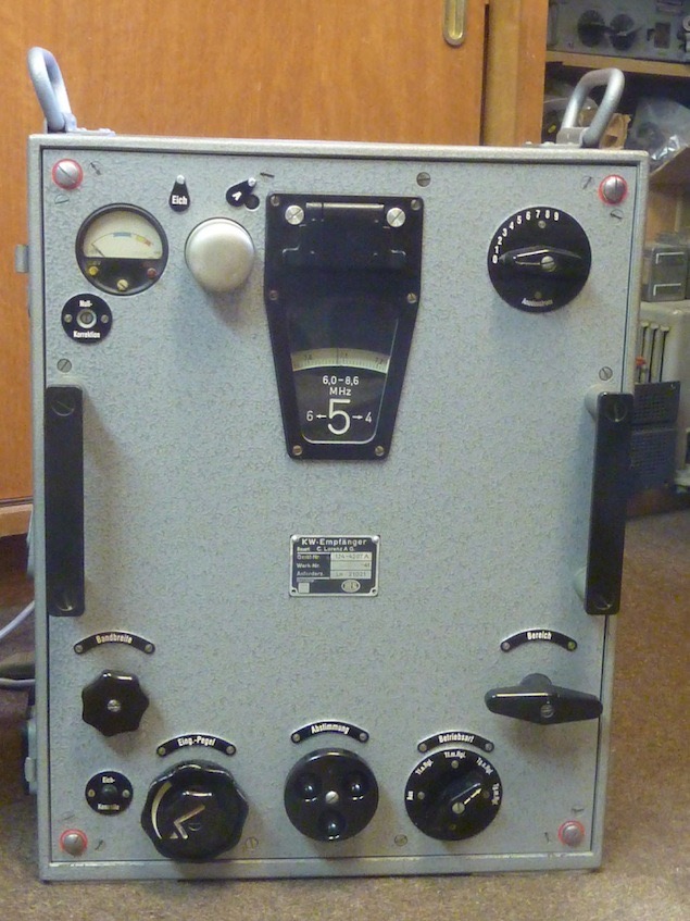
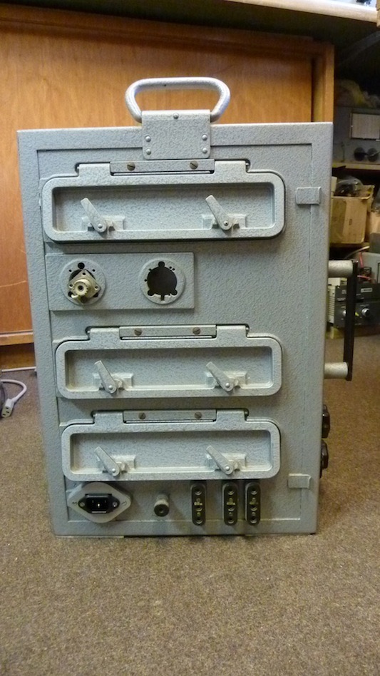
My Ln 21021 Schwabenland
Soviet Schwabenland copy R-673 “ Melnik”
Радиоприемник Р-673 (Мельник/ПРВ)
This receiver is NOT in my collection
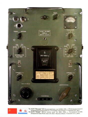
P-673 "Melnik" is Soviet copy of the receiver Ln 21 021 "Schwabenland”. "Melnik" was employed for special Soviet army , marine and purportedly for picking up Sputnik. Model produced during 1949-1960, in about 25000 units, at Petropavlovsk Kirov Radio Works, USSR. 15 tubes 2Ž27, copies of the German RV2,4P700. Coverage 12 KHz-25 MHz in 10 renges. Its low frequencies coverage (12 KHz) was used for connection with submarines underwater.
Bibliography
- Kurzwellenempfanger Ln 21021 (Schwabenland) Peter Treytl October 2008
- Kurzwellenempfänger Ln 21021 (Schwabenland) Gerätehandbuch (Dienstanweisung) D. (Luft) T. 4415, August 1942