Top
OPTIC
Top
1 Working Principle
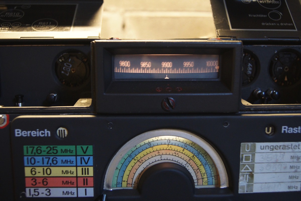
The frequency scale, contained in a microfilm disk, is projected onto a small rectangular ground- glass screen ,illuminated from behind, located above the tuning knob and 'coarse' indicator.
The working principle of the Köln E52 receiver scale is similar to that of a slide projector, as shown in the following Figure 1
The working principle of the Köln E52 receiver scale is similar to that of a slide projector, as shown in the following Figure 1
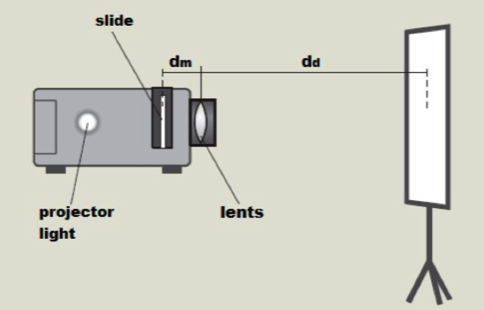
Figure1
Where the light of the projector corresponds to the lamp, contained in the display unit, the slide corresponds to microfilm glass scale and the screen corresponds to small rectangular ground-glass screen.
To better understand how this works would be better first to consider the principles of optics of 'magnification for thin lenses
Let us consider the following figure, which shows the geometric procedure that leads to the determination image hd of a small light arrow hm
To better understand how this works would be better first to consider the principles of optics of 'magnification for thin lenses
Let us consider the following figure, which shows the geometric procedure that leads to the determination image hd of a small light arrow hm
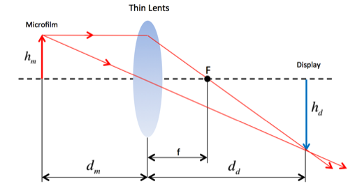
Figure 2
If indicate with dm the distance between the object and the center of the lens and dd the distance between the lens and the image the formula of thin lens is:
The value 1/f is called refractive power of the lens and is measured in 1/m or diopter.
The linear magnification G produced by a lens is defined as the ratio between the length and the hd and length hm of the object
The linear magnification G produced by a lens is defined as the ratio between the length and the hd and length hm of the object

It is proved that the two ratios are equal because the triangles OAB and OCD are similar. The beam path in the optical system of the receiver E 52 Köln is shown in the following Figure 3
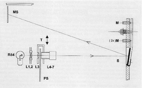
Figure 3
The light radiation, coming from the lamp Ro4, crosses an auxiliary lens (condenser lens), towards the object photographed constituted by the scale (which corresponds to the slide in the projector). The scale has a circular shape and is composed of 5 rows of numbers. Each row of numbers corresponds to one frequency band.
Not far from the scale there is a objective composed of multiple lenses.
In order to obtain a compact structure of the radio is necessary to implement the long path from the objective to the screen through a suitable mirror
Instead of the projection screen of the slide projector is implemented a frosted glass display.
By applying the above equation with the construction data of the optical system of the receiver E52 Köln : dd=21,6 cm and f=1,2cm is possible to obtain, as a result, the object distance:
The distance of optical lens form the object photographed, which corresponds to the scale, must be exactly dm=1,271 cm to produce a sharp image of the marks and numbers on the display.
For optimal focus of the scale it was therefore expected that the objective has an axially threaded body with a ring nut for the locking it once adjusted the focus.
The magnification radio G will be :

This means that the image of the microfilm is magnified on the screen about 20 times [1].
Not all 180 ° are used for mapping of the scale, but only approximately 171-175 °, depending on the range, which corresponds to 95-97% of 180 °. Without this reduction factor all five scales would have a total length of at least 12 meters.
In order to display the scale corresponding to the frequency band utilized the objective is installed on a metallic bar that is moved in height by means of a suitable cam droved by the frequency band selector
The Following Table 1 shows the projected scale location on the disc:
Table1
2 Frequency Glass Scale Positioning
The disc b is fixed on the shaft in which is disposed on its surface round pins c and d on the photographic plate h. The photographic plate h have an approximately semicircular shape and is equipped with a semicircular cut for the shaft a ad a triangular shape notch i on which is rested pin d . The other pin c presses against the other straight edge of the plate x. The position of the plate h is uniquely determined by the pin d in the notch i of the plate h and pin c on the other edge of the plate h. Since there is a single point of contact possible between the straight edges of the plate and the circular pins than is ensured a precise centering of photographic scale plate during reinstallation with plate shifts not larger than 1/1000 mm.[2]
3 The Tuning Module
The die-cast frame of the tuning module contains the variable local oscillator capacitor, two electric motors, a highly accurate mechanical 'memory' for storing receiver frequencies, as well as an unusual frequency read-out device where the frequency scale is displayed on a glass screen situated at the top of the receiver cabinet. The memory, and the method of frequency read-out, must he one of the most sophisticated designs created for a military radio receiver in WWII.
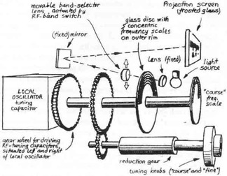
Figure 4
The tuning knob drives, via a mechanical reduction, a sturdy main shaft which controls directly the critical elements. The crucial point about the design is that any backlash between the local oscillator capacitor and the tuning indicators is simply impossible. The reason for this is that the pointer for the 'coarse' scale (the half- round disc just above the tuning knob), the glass disc containing the 'fine' scale, inside the module, and the rotor plates of the tuning capacitor, are all, directly and immovably, fixed onto the same main tuning shaft.
It is this particular concept of using light as a medium, and avoiding any form of mechanical translation, that permits the highly magnified and yet intrinsically rock- solid and precise 'fine' frequency read-out, which makes the E52 such a unique radio receiver. The frequency scale is projected onto a small rectangular ground-glass screen (illuminated from behind) located above the tuning knob and 'coarse' indicator. The total absence of backlash, combined with the highly effective temperature compensation of the associated tuned circuits, as well as an individual frequency calibration at the factory to remove the last component tolerances, result in an accuracy that, certainly in its time, was unheard of.
The information of the frequency scales of all five bands is stored on the outer 6mm rim of a glass disc of about 100mm diameter. This glass disc is safely mounted inside the sturdy framework of the module. The extremely fine print on the disc was achieved by using microfilm techniques. The information is projected by a narrow light beam passing through the selected portion of the glass rim (depending on the position of the band switch) via a lens. The light originates from a low- voltage projection lamp (located just under the projection screen) and is, before it passes through the glass disc, focused by another lens towards the rear of the module where it is reflected by a mirror. Thus, not only a complete projection system has been realised in a compact space, even the projection lamp, a dispensable item like the valves, can he replaced without opening up or moving the radio set [3].
4 Scale Calibration
4.1 Introduction
The procedures for the calibration and manufacture of the E52 Koln scale is based on Telefunken patents [2] [4] , recently discovered by Arthur O. Bauer, and published in his web-site “Foundation for German Communication and related Technologies” (http://www.cdvandt.org).
The know-how of this solution has been passed only in oral way as almost all the related documentation was lost and some of the technicians who took care details of these aspects have died in the Berlin, where was located the Telefunken head quarter, during the last Allied bombing raids.
In 1946 the factory Sachsen-WERK, located in Radeberg, (approximately 20 kilometers north-east of Dresden,) has been stripped of all equipment and documentation, which was later sent to the Soviet Union, including the calibration equipment. Using these materials Soviet Union has been developed some replicas of the Koln receiver in Leningrad research department: "Krot", R-309, R-310 “Dozor” and "Wolnja” that use the same projected scale device.
Figure 5 Sachsenwerk factory completely dismantled shortly after the war
It has also to consider the strict operational secrecy that prevailed at that time in Sachsenwerk-Radeberg. For example [5], the plant manager of production of the short wave transmitter 10 WSC had no knowledge about the production of the corresponding receiver Ukw.Ee in the same factory until the end of the war!
The calibration principle is quite similar to those implemented for the calibration of the US Army Frequency meter BC211, produced during WWII. The calibration method of this device is extensively described in [6].
Details of the various sources are indicated in the last reference chapter 5.
The calibration principle is quite similar to those implemented for the calibration of the US Army Frequency meter BC211, produced during WWII. The calibration method of this device is extensively described in [6].
Details of the various sources are indicated in the last reference chapter 5.
Figure 6 E52 Köln Scale Disk
4.2 Function Basics
The functioning basics of the equipment for realization of the E52 Köln frequency scale essentially use the heterodyne principle [4] and consists in the comparison between the reception frequency of the receiver with a frequency comb harmonics, multiple of the frequency spacing between a scale symbol and the next one.
The comparison is implemented by means of an electronic mixer, followed a proper low pass filter that selects the frequency difference. When the difference between these two frequencies is lower than a low pass filer cutoff frequency, is impressed on a scale a proper symbol by means of photographic exposure.
The symbols on the E52 Köln scale are essentially three:
- Short vertical line
- Long vertical line every 2, 5 or 10 short lines, depending on the E52 Koln frequency range (Table 2)
- Number that indicates the frequency in KHz, placed on top of a long vertical line, at each long line or every two long lines, depending on the E52 Koln frequency range
Table2 Symbols impressed in the scale
Figure 6
Figure 7
All the symbols to be imprinted on the scale disc are reproduced in a film, having a width such as to cover all the circular sector of the disk of the scale where must be imprinted, in a concentric manner, the frequency scales of all bands (Figure7).
The film runs through two rollers W that are rotated after each symbol photographic exposure (figure7).
The rollers W are contained in a camera obscura where there is a gap G, having a width compatible with the maximum width of the symbol, and a height such as to cover all the circular sector of the disk of the scale, where the symbols are imprinted, in a concentric manner, on the scale of all the bands.
In front of the slot a photographic lens J conveys the image of the symbol on the photosensitive material previously applied in one of the two surface side of the scale disk. The photographic lens can be moved, along the slot F, radially among the scale disc, in function of the scale frequency range that must be exposed.
Behind the film is implemented a gas discharge, flash tube L, driven probably by a thyratron circuit, that is switched on when the symbol impression control relay is activated. Flash L can be jointly moved with lens, along the gap G in function of the frequency range selected.
The entire device, previously described, is placed in a camera obscura.
Referring to Figure 6, glass scale is slowly rotated by a motor M connected to the E52 Koln fine tuning Knob shaft TS. The fine-tuning shaft is itself connected at the E52 Koln tuning unit gearbox unit GBU.
In the following Figure 8 is illustrated the overall calibration system functioning basics
Figure 8 Overhaul Calibration System
The local oscillator O frequency of the E52 Köln receiver (red block in Figure 6 and Figure 7), picked up from its oscillator tube Ro5 corresponds to the reception frequency of the receiver plus the value of the intermediate frequency, equal to 1MHz.
In order to obtain the frequency equal the receiver one is subtracted at the local oscillator the intermediate frequency of 1 MHz, using a suitable mixer followed by a proper low pass filter.
The frequency of the reference oscillator (Figure 8): 2 KHz for the range I and II, whereas 5KHz for the other bands, will be sent to a comb generator, which is essentially non-linear quadripole that generate multiple harmonics of its input signal.
The comb generator is usually implemented, as shown in the following Figure 9, as a pulse generator, that is implemented by a multivibrator, triggered by the repetition period of the fundamental signal [6]. Each pulse is of suitable amplitude and of sufficient short time duration to ensure a spectrum substantially equal amplitude harmonics up to the upper limit of the receiver frequency range.
Figure 9 Comb Generator
From this frequency comb was picked up only a small bandwidth of each E52 Köln range, in order to avoid saturation of the following mixer stage, through a five band-pass tracked filter preselector bank, connected to the same motor M (Figure 6). This tracking preselector was probably similar to those implemented in E52 Koln receiver.
The frequency fr and fx will be sent to the mixer (Mixer 2 of Figure 8).
At the output of the mixer is extracted the difference between the frequencies at its input, by means of two different types of low-pass filters [4]:
The output of the two low pass filters is then rectified and opportunely amplified, in order to be able to drive electromechanical automatic controls.
The functioning basics is the following:
Before to proceed of the scale calibration the five local oscillators of the E52 Koln receiver should be calibrated using a pre-calibration scale disk [8] than the receiver was placed in a camera obscura and connected at the calibration machine, described showed in figure 8. A photosensitive scale disk was than applied at the receiver.
The receiver oscillator O was slowly tuned by a motor M. The motor M was arranged so that when the receiver is in the proximity of the next mark, and than the frequency difference was about 500 Hz, a beat note was passed, the motor went slowly and at 70 Hz beat note the motor was cut out and the inertial system brought it down to zero beat, than the relay R activate the gas discharge, flash tube. The flashlight projects an image of the appropriate symbol on to the sensitized plate. The projector film was than moved to the next position and the motor was automatically re-stared. This exposure cycle was repeated until all the symbols of the frequency band has been exposed on the plate disc sensitized
When the scale of that frequency band was finished was than necessary:
- move the objective radially along the scale in the proper position
- invert the rotation of the film roller
- select the proper calibration frequency at the input of the comb generator: 2KHz for band I&II or 5KHz for band III, IV & V
- select the proper tracking preselector filter bank, located after the comb generator output.
Table 3 Number of Marks on The scale
In the following Figure 10 is shown how would have been synthesized the frequencies required to calibration device.
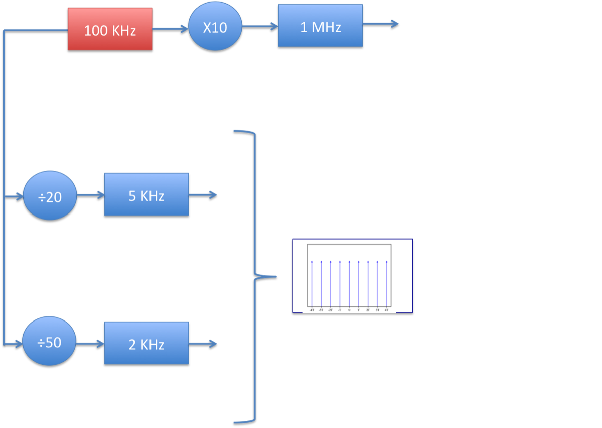
Figure 10 Frequency Synthesizer
The two required frequencies are synthetized by means of frequency division of 100KHz crystal oscillator in order to obtain higher frequency spacing accuracy [6].
A 100 KHz crystal oscillator was probably also used for obtain 1MHz IF frequency by means of frequency multiplication x 10
The "calibration machine" was a production apparatus that, after a few hundred or thousand units produced was surpassed after September 1944.
Monitoring production results, was observed that, applying calibration trimmers at the oscillator circuit of each band the deviations between the scale was so low that it was not worth the effort to spend time and energy on the individual calibration of the scales.
In fact the use of the calibration machine had significantly limited the number of radios produced daily at Radeberg Factory ; 6-12 with average 8. [5]
Since September 1944 than started the production of “unified scale” able to meet a relaxed specifications. Unified scale, opposed to individually calibrated
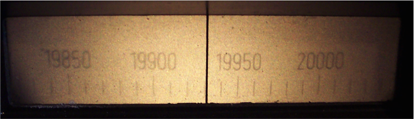
Figure 11 Unified Scale
Individually calibrated scale tolerance was 0.5% while for the unified scale tolerance has doubled to nearly 1 KHz for 1 MHz
4.3 Multiplier Implementation
Like for the comb generator the 100KHz reference quartz clock is followed by non-linear quadripole .The 10th harmonic is picked up by a 1MHz band pass filter
The device can be simply implemented by a 1MHz selective tube amplifier polarized in the non-linear behavior as class C amplifier.
The device can be simply implemented by a 1MHz selective tube amplifier polarized in the non-linear behavior as class C amplifier.
4.4 Divider Implementation
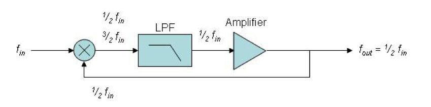
Figure 12 Frequency Divider
A regenerative frequency divider, also known as a Miller frequency divider, mixes the input signal with the feedback signal from the mixer.
The feedback signal is fin/2. This produces sum and difference frequencies fin/2, 3fn/2 at the output of the mixer. A low pass filter removes the higher frequency and the fin/2 frequency is amplified and fed back into mixer.
The feedback signal is fin/2. This produces sum and difference frequencies fin/2, 3fn/2 at the output of the mixer. A low pass filter removes the higher frequency and the fin/2 frequency is amplified and fed back into mixer.
5 References
[1] Luft-Boden-Einheitsempfänger E52 Prüfung-Reparatur-Abgleich Teil II: Mechanik, Optik, HF Conrad H. von Sengbusch DJ2DK, Ulrich Wintzer DL7FZ
[2] Patent by Alwin Weber Telefunken Gesellschaft für drahtlose Telegraphie m.b.H. in Berlin-Zehlendorf Mit einerphotographischen Schicht ausgestatteten Skalenträger für Empfänger- und Sendegräte Application date 24 November 1939 granted 29 January 1942 Available at http://www.cdvandt.org
[3] PA0SE Dick Rolema German World War II Radio Equipment - Köln E52 receiver
[4] Patent by Kurt Protze; Alwin Weber and Fritz Semerau: German Patent De691884 “Selbsttätige Eichvorrichtung, Eichanlage - Kalibrier- Gerät”. Available at http://www.cdvandt.org
[5] Werner Thote : “Funkgeschichte” magazine n°79, 1991
[6] David Sunstein, Josef Tellier: “Automatic Calibration for Frequency Meters” Electronics Magazine May 1944
[7] Bolt, McIntyre,Veevers, Whitehouse :Britisch Intelligence Report B.I.O.S No. 1228 HF Insrtruments and Measuring Techniques” page 3. Available at http://www.cdvandt.org
[8] Conversation with Prof. Dr. Gottfried Domorazek: E52 Köln expert