Function
The central design element of the manual drive is shaft (A) that emerges through the front plate (B) with a conical head. At the opposite side of the shaft mounted in the rear is plate (C) rigidly connected onto the oscillator capacitor trough a cylindrical element. The shaft runs in bearings and is fixed with screwed ring (D).
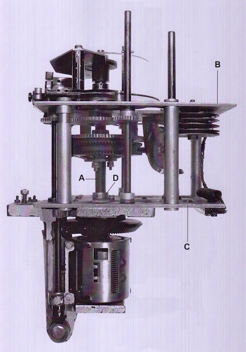
On the manual drive shaft (A) is present a cogwheel (E) for the grob frequency tuning . When it is installed, the Novotex cogwheel (F) and the connection of gear (E) is not visible. At the front of the bearing is fixed a five-pointed star plate spring (G) which pushes against the gear wheel (E).
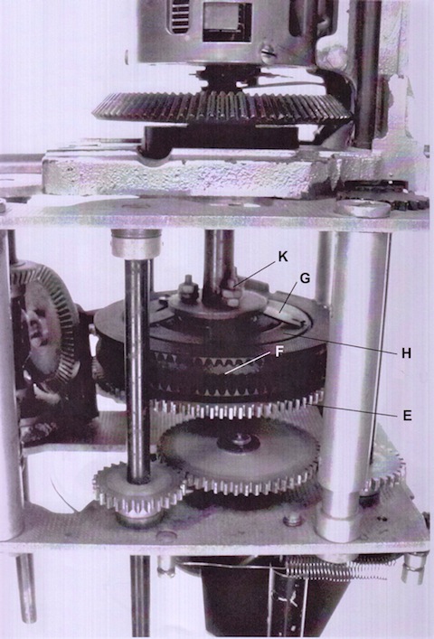
The dual-sided pressure on the wheel worm is absorbed by inlaid brass disks, plus the power of the five-star by an interposed spring steel ring (H) is uniformly distributed over the circumference. By the pressure of the star plate over the steel ring the transmission of the rotary motion is ensured. Between the two gears there is then a friction clutch that transmit a rotation of the worm wheel at the main shaft, but with the pressure of the Grob tuning knob it is possible to directly interconnect with wheel worm (E) leaving that the worm wheel work remains steady with auto-blocking device.
The friction clutch has been implemented in different manner, in some productions series the drives have the contact pressure adjustable in others not. The figure shows the version with the adjusting nut (K), SW6. After a certain range of production series, the average torque value was calculated and the adjusting nut (K) was no more present.
Grob Tuning (Grobtrieb)
A rotation of the shaft (L) is transmitted to the small gear wheel (M). This pushes, through the gear wheel (N), whose diameter is not significant , the Grob frequency tuning gear wheel (E) and thus the main shaft (A). The reduction factor of the course tuning is 6:1. If the Grob tuning rotates "moderately hardness" it is possible to apply a thin layer of grease in the pressure areas of wheel worm since the Novotex does not admit grease.
Fine Tuning (Feintrieb)
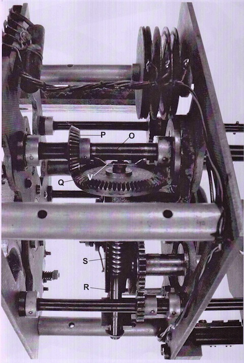
With the rotation of the 8-mm-shaft (O), the bevel gear (P) is consequently moves, which in turn drives the big bevel gear (Q). This is part of the shaft (R), which is connected onto the gear screw (S).
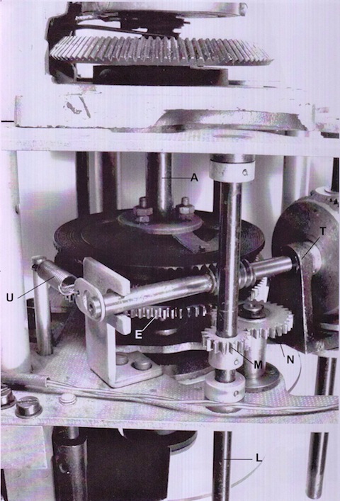
The rotation of the gear screw (S) moves with a very large reduction of the worm wheel then through the friction clutch, already described, acts on the main shaft. The shaft (R) is connected only on one side, towards the big bevel gear (Q), by means of bearing bracket (T). On the other side the shaft (R) is bounded in the slit of bearing bracket (T).
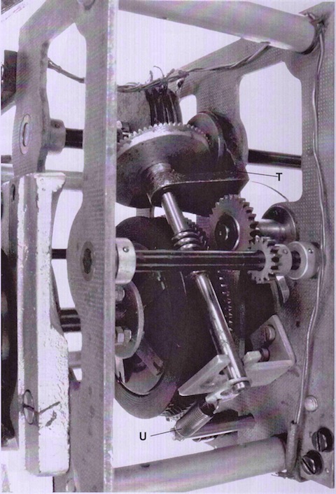
A tension spring (U) pulls the shaft versus the slit of a bearing bracket (T). This action pushes the gear screw (S) versus the cogwheel.
A shaft pin is put in front of the bevel gear with a spring bridge (V) supported by the shaft (O). A variant of this construction is a small brass socket, located on the pins, to improve the contact. This helps to drain static charges and thereby prevent noise during tuning. The reduction factor of the fine-tuning 180: 1
ERRORS AND REPAIR
With time passing mechanical malfunctions may appear caused by wear, grease gumming, moisture storage, shock, tampering, etc
The most common mechanical malfunctions are :
1) Grob Tuning difficulty (Difficult knob rotation)
2) Fine Tuning difficulty (Difficult knob rotation)
3) Fine Tuning idling rotation
The E52 Koln instruction manual recommends not to lubrificate the driving mechanics, but the manual did not provide for the maintenance of the radio after more than 65 years. After the war most of these radios were used for 20 years in 24-h-monitoring service. With such working stress also the best oil resinify and then ball bearings and other mechanisms (frictions etc) are pasted.
During the restoration work it is recommended to disassemble the projection microfilm disk in order to avoid oiling on it.
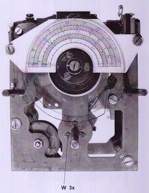
Stubborn Grob tuning rotation
After having dismounted the mainspring (U), loosen the three screws (W) allocated on the front plate with its fixed bearing bracket of the worm shaft it is now possible to move the shaft (R), with the long worm shaft (S) from the gearwheel. Sometimes it is possible that the ball bearing is stuck on the front plate. In this case is necessary to use spray oil 1) and wait until the oil penetrate.
The Grob tuning gear must now be turning easily. If not, put spray oil on the bearings of the shafts (A) and (L) and the intermediate gear (N). After sufficient oil activity time (about 20 minutes) now the Grob tuning gear should be moved easily. Then stuck the rotation the Grob tuning worm wheel and try to rotate the worm shaft.This rotation is stopped by the friction brakes, but it should always be possible to rotate it albeit with some difficulty. In case it is not possible to rotate it, this means that the friction disks are being stuck. In this case it is necessary to remove the five-pointed star plate spring (G) and the above steel ring . The fixing of the five-pointed star plate spring (G) could be different: through three head screws or three self-locking nuts (SW6) on threaded bolts.
After removal of the worm wheel from the Grob tuning gear wheel the connecting clutch and bearings surfaces can be cleared.
This clearing can be done by Surgical Cotton (Q-Tip) or cotton swab soaked in gasoline ether, alcohol, isopropyl alcohol, etc After the residues have been removed is necessary to re-greased sparingly the coupling surfaces and the approach to the worm wheel bearings.
The best grease for this application is technical Vaseline, ATLANTIC or "instrument grease" that was produced in DDR.
The assembly begins with the possibly existing threaded bolt. Here for safety it is possible to use LOCTITE . In order to fix the ring with the three screws to the five-pointed star plate spring (G) it is necessary a suitable tools due to limited spaces inside the tuning box. After the screws were handled with Loctite wait at least 20 minutes until the glue dried.
The worm wheel is pushed back versus the bearing bracket (T), then fix the ring with the three screws to the five-pointed star plate spring. In case of three self-locking nuts (SW6) on threaded bolts it is necessary to search for a middle and balanced position before fixing the security locknuts.
Then, again, stuck the rotation of the Grob tuning worm wheel and try to rotate the worm shaft This rotation is stopped by the friction brakes, but anyway it should be possible to rotate it.
Finally, fix again the bearing bracket (T) of the worm shaft, and then mount the spring (U), with its tongue back into the worm shaft.
Difficulty Fine Tuning Problem
Since the fine tuning is a part of the Grob tuning, it is sufficient ,after the preliminary work on the approximate tuning functionality, to use spray oil on the bearings present at the front and rear plate : bearings of the shaft (A) and bearing bracket (T) . Wait some minutes until the oil penetrate internally. Finally apply at all cogwheels and the gear screws a very thin layer of grease 1) 2).
Rotation play (backlash) of the fine-tuning
This problem can have two possible causes:
1.insufficient push of the gear screw (S) versus the worm wheel (F)
2. axial offset of the worm shaft (R)
Both errors affect the same and are recognized as follows:
Slightly rotating the approximate tuning knob can be easily perceptible loosening from the small cogwheels (M) and (N) normally initially stopped, before first rotates the Grob tuning cogwheel. Then if now together with the approximate tuning cogwheel rotation beginning also there is a slightly rotation of the screw wheel there will be a second loosening There is no immediate self-locking with the worm shaft, then it will be little bit dragged with a friction. At the projected scale display, with the receiver in working condition, is possible to estimate the mechanical play .The backlash (mechanical play) can be from 1 / 4 to 1 / 2 of the scale interval.
Notes refer to point 1
If the worm shaft does not enter in the teeth of worm wheel first of all is necessary check the angle at point on interconnection between the bearings on front plate. Among the three Allen screws must be located internally toothed wheels, which should be renewed. While the screws are tightened again, the screw firmly pressed against the worm wheel. After this it is necessary to check whether the mainspring (U) with the sheet metal folds into the groove of the worm shaft is hinged and is exerted on the screw axis enough traction. Eventually the mainspring must be changed. The fine adjustment should now working correctly. To be more precise the worm wheel having a continuous self-locking.
Notes refer to point 2
If the worm shaft push trough the worm wheel as described at the previous Notes 1 may be a second problem: when you rotate the tuning knob the worm shaft (R) may move perpendicular to its axial direction. This problem is maybe due to the bearing wear that interconnects worm shaft (R) from cogwheel (Q). There are two different ways to repair it: The first consist in remove the bearing bracket (T) with worm shaft (R) . Before doing this it is necessary that all the split pins of the shaft (O) must be removed. Then insert a thickness on the side of worm shaft . The second step consist in removing the worm shaft (R) from the cogwheel (Q) and insert a thickness on one side between the bearing and cogwheel (Q).
The two options described above are both strongly not recommended, because there isn’t a reliable solution for remove all the split pins of the shaft (O). Furthermore if you try to do that the projected scale could be damaged. The glass scale removal, in order to avoid damaging it would also be and additional hard work.
Then the following procedure is recommended:
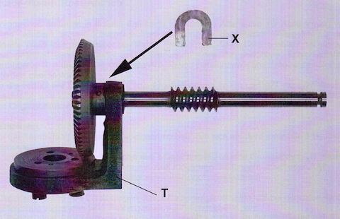
First must be removed the three screws of the bearing bracket (T) and mainspring (U).Then the bearing bracket (T) can be slightly rotated, thereby achieving better access to the back of the ring gear. By means of a feeler gauge it determines the amount of shaft clearance. Then it is necessary to obtain from a sufficient thin brass or bronze plate a cut out strip with a U-shaped (X) made in accordance with the shaft diameter. This sheet must be completely debarring.
The U-shaped metal sheet must be inserted between the bearing bracket (T) and cogwheel (Q) and pushed to the ends are bent by 90 ° so it will be fixed. This solution is not perfect from a mechanical point of view, however it works fine, while the three screws are tightened again, the screws firmly pressed against the worm wheel .
As a result the two options described above briefly, the clearance is reduced in the tight angle drive, the remaining clearance is not related to idling rotation
It has already been mentioned, the axial play of 8-mm-shaft (O), which in some cases has already compensated at the factory through a U-shaped (X) like has been described. Eventually, due to usage it could be necessary to replace U-shaped (X) with more thickness in order to reduce the clearance. In principle, however both the drives although in good condition maintain a slight clearance.
Bibliography
- Luft-Boden-Einheitsempfänger E52 Prüfung-Reparatur-Abgleich Teil I: Netzteil, ZF, NF ;Teil II: Mechanik, Optik, HF Conrad H. von Sengbusch DJ2DK, Ulrich Wintzer DL7FZ
- L.Dv. 702/1, Heft 167, Luftnachrichtentruppe, Teil 1, Ausbildung am Gerät, Der Empfänger E 52, 1,5-25 MHz, Aug. 1943
- Luft-Boden-Einheitsempfänger E 52 b-2
- Luft-Boden-Einheitsempfänger E 53 Teil 1, Kurzbeschreibung und Betriebsvorschrift