Beginning in 1937 Telefunken also became involved in the development of a small radar system for short-range location and identification. The resulting system, known as the FuMG 62 (as well as FuMG 39T, although this may have referred only to the Darmstadt), was demonstrated to Hitler at Rechlin in July 1939. The Telefunken team developed an accurate system based on a klystron microwave tube operating in the range of 54 to 53 cm (553 to 566 MHz) – an extremely short wavelength for the time – with a pulse length of 2 microseconds, a peak power of 7 to 11 kW, and a PRF of 3,750 Hz. It had a maximum range of about 29 kilometers, and was accurate to about 25 m in range. Würzburg used a 3 m parabolic dish antenna mounted on a wheeled trailer, and the dish could be "folded" along the horizontal midline for travel. The system was first accepted into service in 1940, and eventually 4.000 of this basic layout were delivered.
Several versions of the basic Würzburg system were deployed over the course of the war.
Wurzburg A
The first, Würzburg A, was operated manually and required the operators to pinpoint the target by maintaining a maximum signal on their oscilloscope display. Since the signal strength changed on its own for various reasons as well as being on or off target, this was not very accurate, and generally required the use of a searchlight to spot the target once the radar had settled on an approximate position. Nevertheless one of the very first Würzburgs claimed a plane in May 1940 by orally relaying commands to a flak unit. An experimental
Wurzburg B
Würzburg B added an infrared detector for "fine tuning", but in general these devices proved to be unusable and production was discontinued.
Wurzburg C
Type FMG 39T (C) is a modification of the basic Wurzburg design. It has a rotating dipole with synchronous antenna and indicator switch- ing. Three CRT's are used: one large one with circular time base for range measurement, and two smaller ones (azimuth and elevation tubes). Minimum angle of elevation for cover is 50 and for height-finding is 100 above the optical horizon for inland sites. A hand-rotated circular scale, calibrated from 2 to 16 km, is also pro- vided. Setting the pointer of this scale to the same range as that indicated in the range tube brings the correct echoes into the smaller tubes for aiming.
There is also a push button by means of which the operator can change the pulse repetition frequency from 3,750 to 5,000 Hz in order to enable the aircraft IFF to function.
Type FMG 39T (C) is used at most Seetakt sites in northwest Europe. It is used mainly for Flak control, for searchlight control (via the plotting instrument "Malsi"), height-find- ing for aircraft reporting, or as stand-by in interception control. This set was introduced into service in 1941. The characteristics of this equipment are as follows:
RANGE (Km): From 1,6 to 40.
FREQUENCY RANGE (MHz): "A" band, 550 to 580; "B" band, 470 to 490; intermediate band, 545 to 555; 520 to 590 also reported
PULSE RECURRENCE FREQUENCY (Hz): band, 545 to 555; 520 to 590 also reported. 3,750 increased to 5,000 when used with IFF.
PULSE LENGTH: 1 to 2 microseconds,
ANTENNA: Sheet-metal parabolic 3 m diameter, with wide-band dipole of sheet- metal blades; blade-fixing holes slotted for adjustment at approximately 0,5 m or 0,6 m working. Alternative narrow-band dipole on some specimens. Front reflector is 8-cm strip of sprayed metal on Bakelite disk, 7,8 cm in front of dipole. Common T&R.
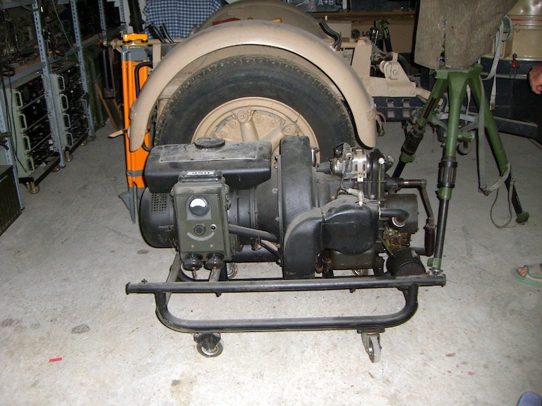
POWER SOURCE: 90 to 380 volts, 40 to 60 Hz ac from power lines or standby motor- generator set or both.
SIMILAR SETS: Wiirzburg : FMG 39T (A) and (D) and FMG 39T Riese (Giant).
POWER INPUT REQUIRED: 3.3 kw .
POWER OUTPUT: 7 to 11 kw (peak).
TUBES (type and number): 75 tubes in transmitter-receiver unit FuSE 62 as follows: One LS 80, twelve LS 50, twelve LS 20, four LD 2, thirty-four RV 12, one LV 1, two LG 1, one LG 2, one LB 13/40, one LB 7/15, four neon lights TE 4, one quartz crystal OEK 1, and one stabilizer STV 150/15.
TRANSPORTATION: Mobile; it can be carried in truck or trailer.
TYPE OF PRESENTATION: Three CRT's: one large, with circular time-base for range measurement and two smaller ones, elevation and azimuth tubes.
DATA OBTAINED: Range, elevation, and azimuth,
ACCURACY: Of range, 124,7 m; of azimuth, 0,2° of elevation, 0.2° (estimated).
Over-all dimensions of set: 2,6 m Height; 3 m Width; 5m Length
Wurzburg D
Type FMG 39T (D) is the latest model of the small Wiirzburg, It was introduced into service in 1942.
Like types (A) and (C), it is equipped with IFF. In addition, it has the facility for precision range finding, provided by an additional CRT.
When the IFF is in operation, the PRF is changed from 3.700 to 5.000 Hz; this apparently makes the radar completely inoperative during interrogation. The signal at 5.000 Hz actuates FuG 25, which transmits a 20 MHz signal with keyed 1.000-cycle modulation, which is received on two dipoles mounted on either side of the parabolic. From these antennas, the signal passes through a commutator to insure that the signal is from the plane at which the parabolic is pointed. A normal receiver is then used to give aural indication (headphones) and visual indication (meter). A small antenna placed on the parabolic indicates by means of diode. rectification and a meter that the set is transmitting; a PS 62 test transmitter is used to show that the receiver is in operation.
The transmitting tube is a triode, type LS 180, with approximately 8-kw peak output power. The receiver is a double super heterodyne.
This type of Wurzburg is probably used for detecting surface vessels. It is used also for Flak fire control, gun laying, searchlight control, and height finding for aircraft reporting and as stand-by in ground control of interception
The characteristics of the FMG 39T (D) are as follows:
RANGE (Km): From 1,6 to 40.
FREQUENCY RANGE: (MHz): “A” band 550 to 580; "B" band, 470 to 490; intermediate band, 545 to 555 ; 520 to 590 also reported. PULSE RECURRENCE FREQUENCY (Hz) :
3,750, increased to 5,000 when used with IFF.
PULSE LENGTH: 1 to 2 microseconds,
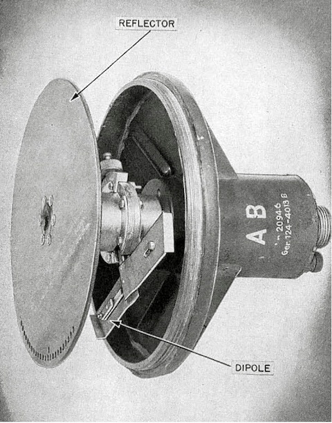
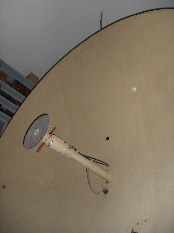
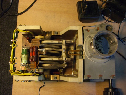
In the picture details of the rotating “Quirl” dipole. The flat reflector faces toward the target, away from the main antenna reflector.The rotating dipole broadcast toward the disk, witch reflects the signal toward the main antenna, witch focuses the signal into a narrow beam facing the target.
ANTENNA: Sheet-metal parabolic 3 m diameter, with wide-band dipole of sheet- metal blades; blade-fixing holes slotted for adjustment at approximately 0,5 m or 0,6 m working. Alternative narrow- band dipole on some specimens. Front reflector is 8-cm strip of sprayed metal on Bakelite disk, 7,8 cm in front of dipole.
POWER SOURCE: 90 to 380 volts, 40 to 60 Hz ac from power lines or standby motor- generator set or both.
SIMILAR SETS: Wurzburgs : types FMG 39T (A), (C), and FMG 39T Riese (Giant).
POWER INPUT REQUIRED: 3.3 kw,
POWER OUTPUT: 7 to 11 kw (peak).
TUBES (type and number): 75 tubes in transmitter-receiver unit FuSE 62 as follows: one LS 80, twelve LS 50, twelve LS 30, four LD 2, thirty-four RV 12, one LV 1, two LG 1, one LG 2, one LB f3/40, one LB 7/15, four neon lights TE 4, one quartz crystal OEK 1, and one stabilizer STV 150/15.
TRANSPORTATION: Mobile, mounting similar to Freya Limber model.
TYPE OF PRESENTATION: Four CRT's, for azimuth, elevation, and range as in types (A) and (C). A fourth tube has been added for finer range readings; it has a single horizontal trace on which, by means of a control knob, an enlargement of any given sector of the range tube can be dis- played and range in km read off in a small window indicator.
DATA OBTAINED: Range, elevation, and azimuth
ACCURACY: Range accuracy approximates 10 m; D/F accuracy 0,2° at all ranges. Precision ranging is accomplished by phase- shifter operating on the sinusoidal (30-kHz crystal-controlled) deflector voltage of the range strobe tube.
A variant of the FMG 39T is the FMG 41T, which resembles the FMG 39T (D), except that the parabolic sometimes has a scoop like extension at the bottom, presumably to cut out ground echoes.
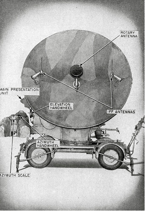
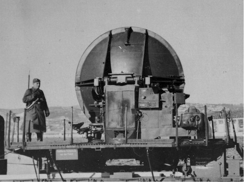
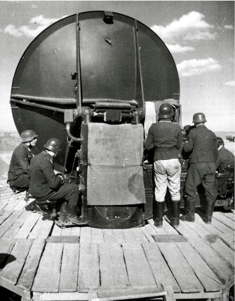
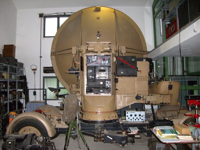
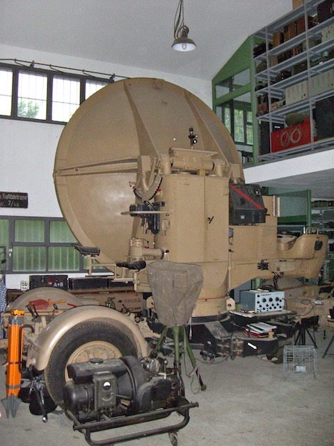
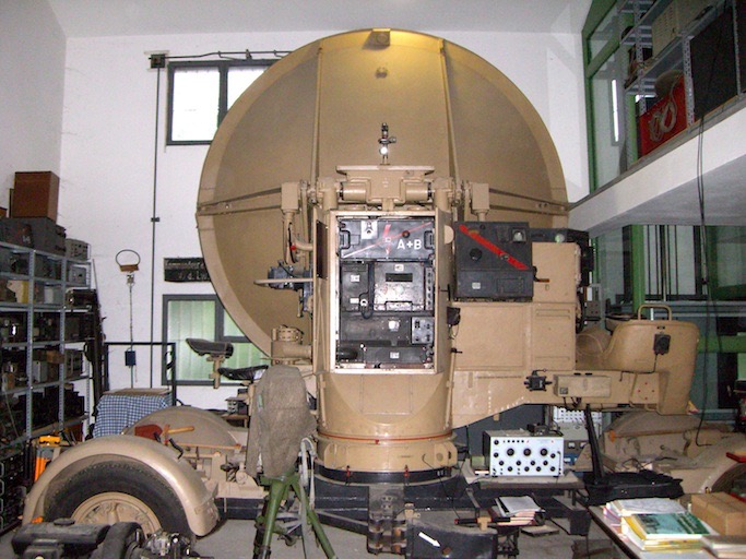
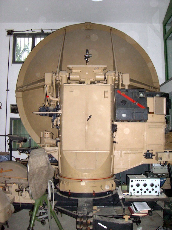
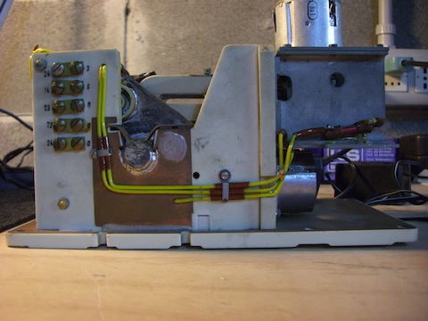
Front view of Würzburg type D (FuSE39 D or FuMG62 D). The IFF antennae might originate from an early type D or maybe type C, as the odd Würzburg IFF had been replaced by FuG25a (Erstling), also known as "Gemse - Kuh". All German radars were adapted to this IFF standard. The rotary dipole provided pencil-beam-scanning, which is also known as conical-scanning. It was originally invented by Wilhelm Runge and Stepp of Telefunken
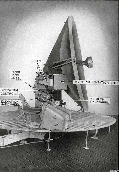
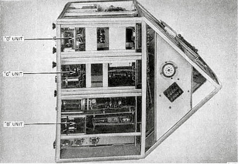
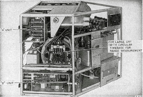
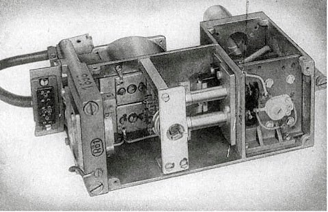
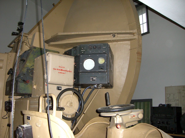
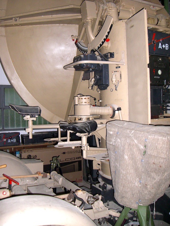
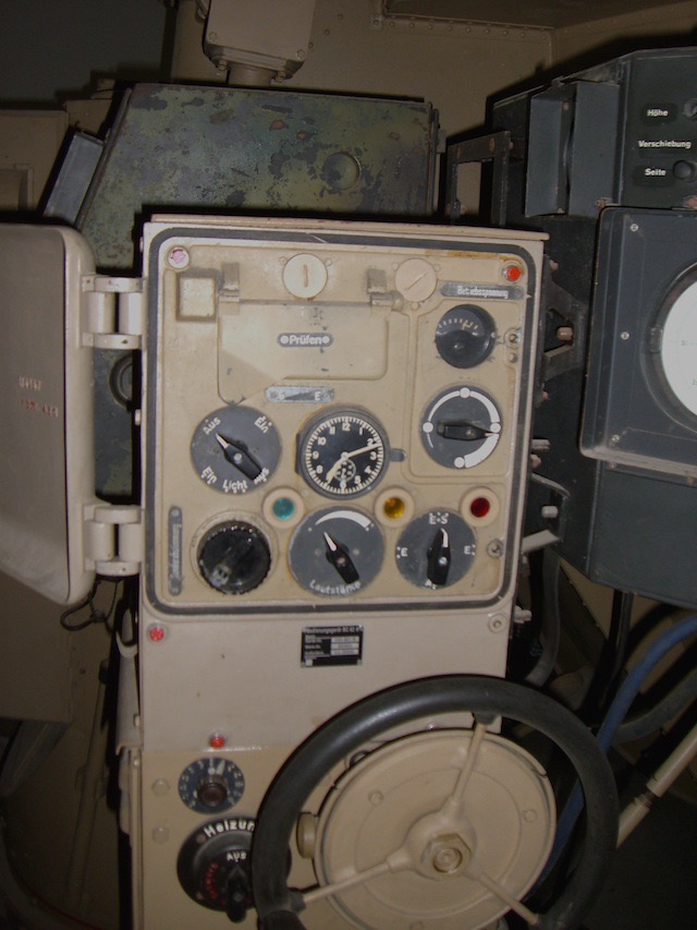
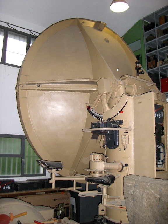
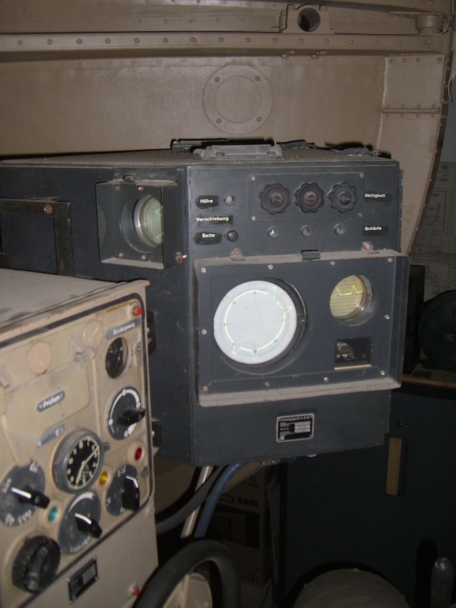
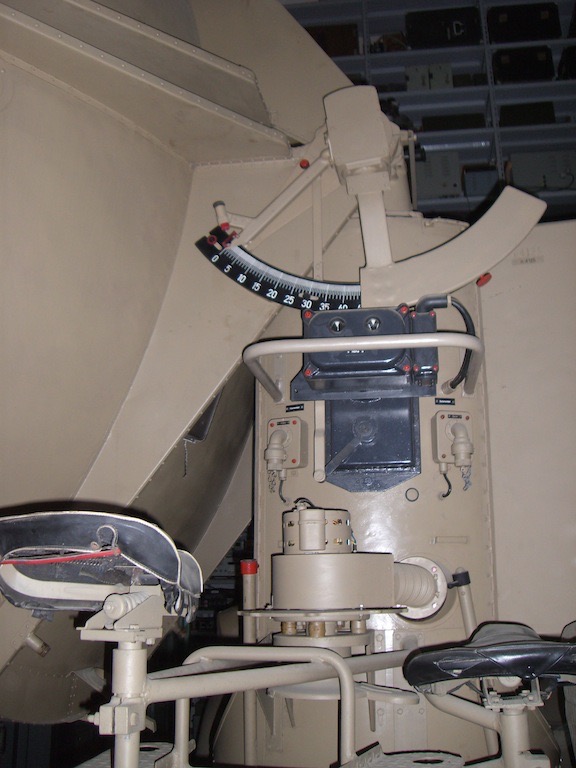
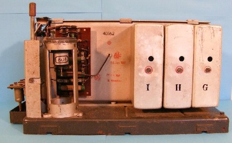
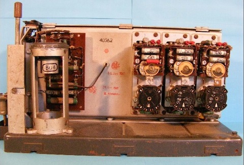
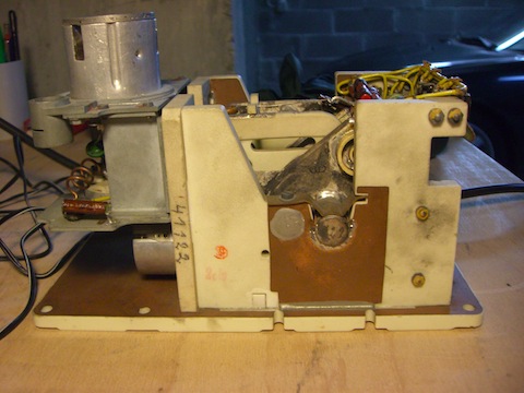
Shown is, a side view of a Würzburg FuSE62 D. What they call 'main presentation unit', is the odd OSZ62. The main presentation unit is type ANG 62. But it proved that it was more convenient to continue the use of a second presentation CRT.
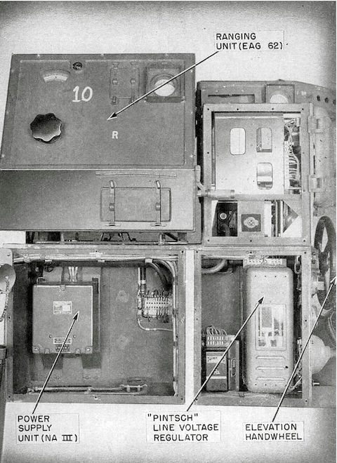
The fine ranging (measuring) unit is type EAG62. The unit right of it, in the background, is the coarse range - azimuth and elevation display ANG62.
The 'Pintsch line voltage regulator' is of the 'carbon-pile' type and reduced the 220 volt mains to a stabilized 180 volt a.c. Power supply NA III provided negative voltage for (valve)grids. The elevation wheel had to be controlled by a special elevation operator, which information he could discern from the small CRT display, just visible in the upper part of ANG62
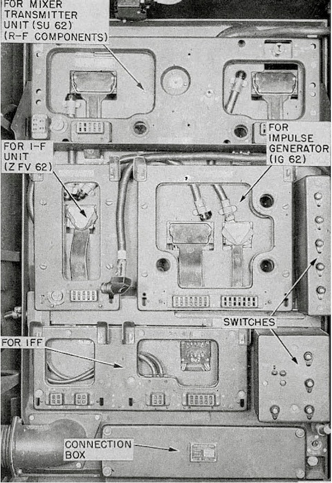
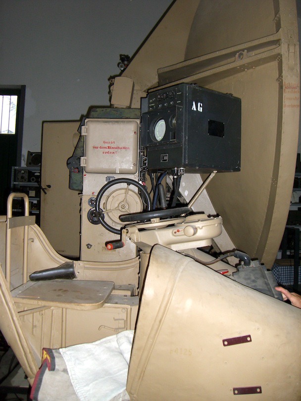
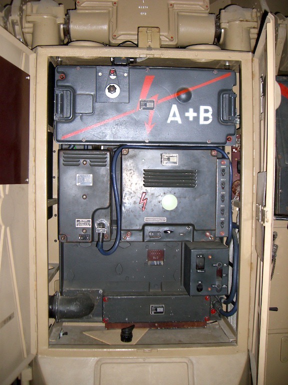
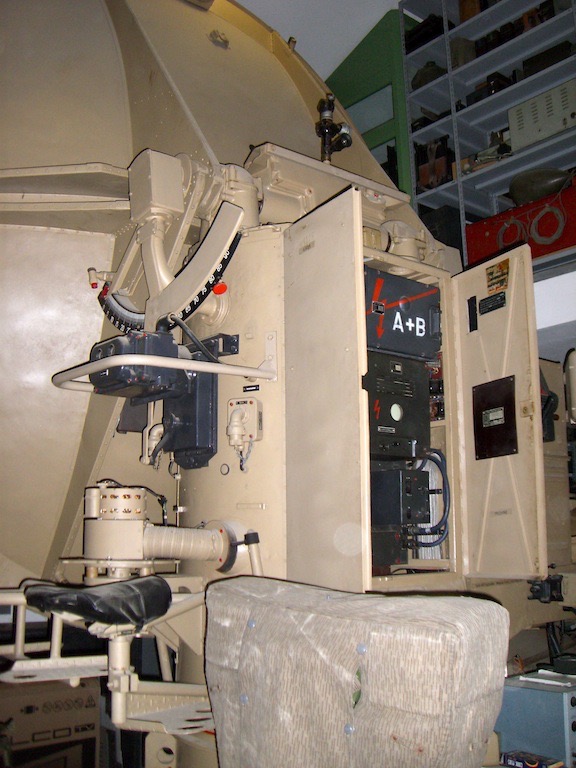
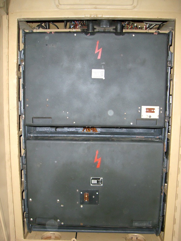
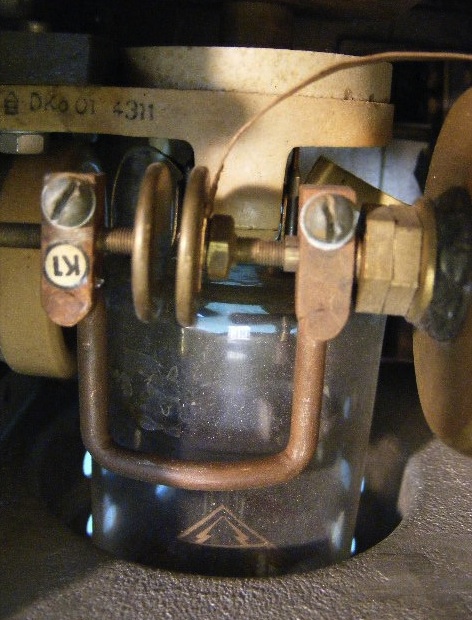
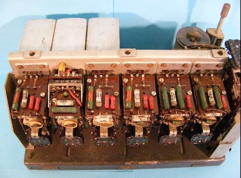
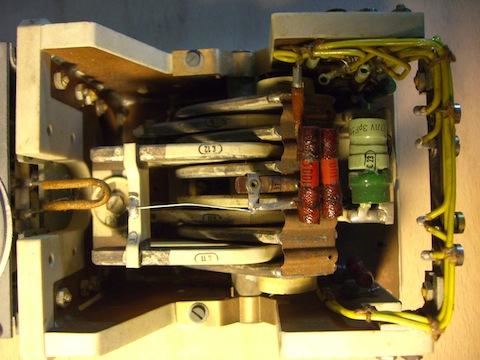
One of the striking advantages of German electronic design is, their modular concepts. The mounting frames constituted convenient maintenance, as units (modules) could easily be changed. All mounting frames (Aufhängerahmen) were linked onto the interconnecting-wiring by means of 'flat cables'. The pointer 'for IF unit ZFV62' is pointing at such a flat-cable connector. Its accompanied flat-cable is recognisable. We can see that all frames were connected this way. The exception is the frame marked for 'IFF". This is why I questioned from what period (1942 - 1944) this particular radar set is? Originally, Würzburg utilized a quite odd IFF system and after say late 1942 or early 1943 this IFF system had been made redundant. After German radars were jammed effectively, this space was used for 'Goldammer' and its successor anti-jamming devices (ECCM)
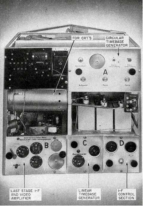
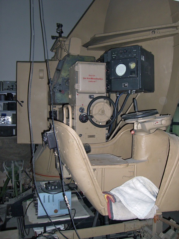
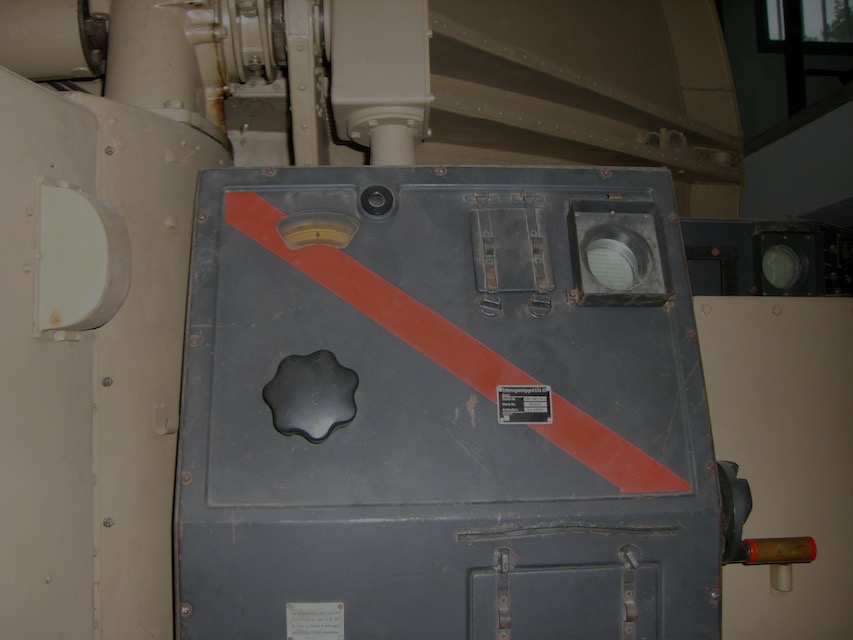
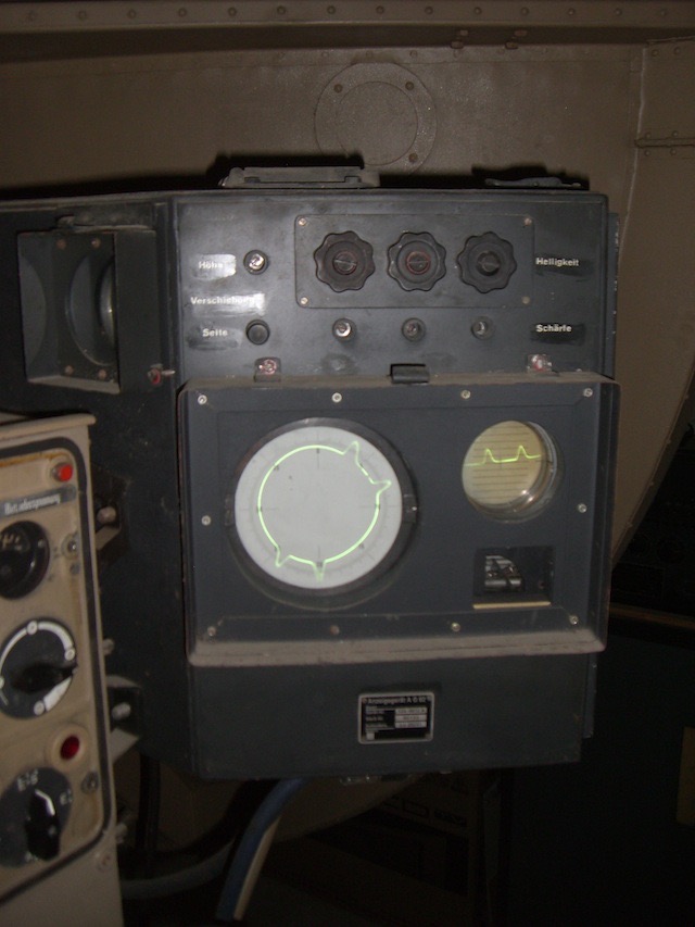
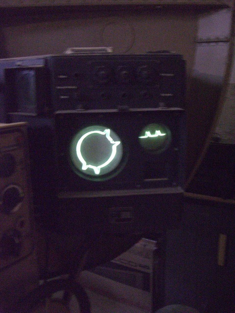
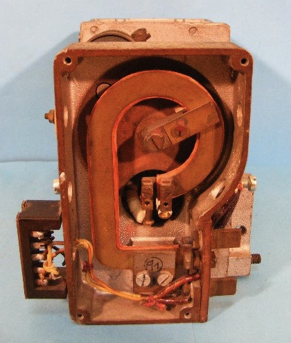
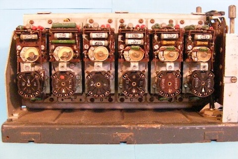
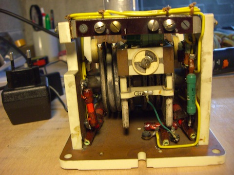
Side vision of the right-hand side of the ANG62 display unit. Module A is the circular time base generator/deflection amplifier. The coils of the circular magnetic deflection-yokes were tuned at 3750 Hz. The two coil sections were, however, fed 90° out of phase. This technique, by the way invented by Manfred von Ardenne in the early 1930s, guaranteed an extremely linear circular time base-line. 'T' is the lever of the 'Taunus' mode switch.
Taunus differentiated the displayed video pulses, as to indicate the slope response of radar-signals. Window (now called Chaff) gave reflections with a weak slope and targets was expected to provide steeper signal slopes. Module 'D' was not employed for IF control, though, had sometime two functions: first it was used to provide a dark-spot marker in the main range screen, as to indicate where the fine-range operator was actually looking at. Later it was left out and this unit was converted to carry the so-called 'Neurnberg' system, which used gated-signals. The fine-range operator (EAG62 operator) had in the centre of his screen a blanking marker.
This marker pulse was used as to de-block (gating) a LF-amplifier (creating a window). When a target was being observed, the video signal (the target signal) was sent to a pair of headphones. The prf of Würzburg was 3750 for the small set and 1875 Hz for Giant Würzburg and both signals are within the human audio spectrum. Aircraft of those days were generally using propellers and the radar signals were also chopped or modulated by its rotation frequency. This video or audio spectrum had to be listened for, as only aircraft could reflect such signals. Whereas Window never could fake German radar signals that way. Its principle is known as 'Propeller modulation', and was invented about 1934 in the US. Though, they themselves hadn't employed these techniques. Both, Taunus and Neurnberg helped the radar operators to discern between fake or real radar signals. However, despite these new efforts, results were very dependant upon the skills of German radar operators.The Neurnberg and Taunus features were often indicated(marked) with the characters 'T' and 'N'.
Mixer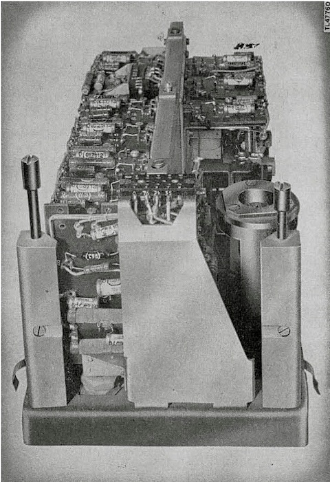
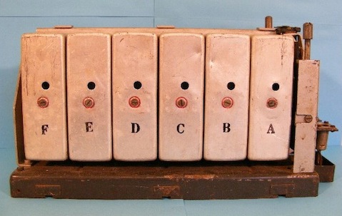
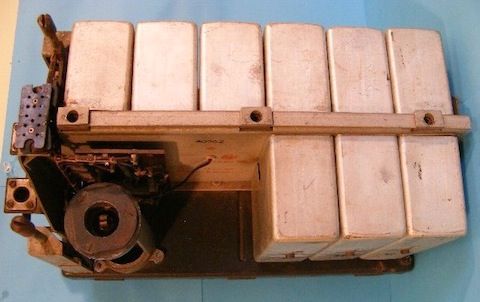
IF Unit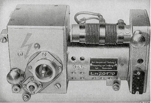
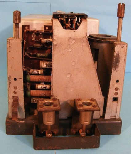
Tx Unit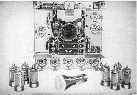
Impulse Generator
Wurzburg Radar in Italy
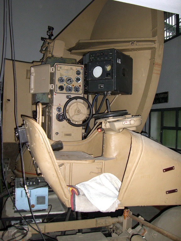
The following pictures are related a completely restored Wurzburg Radar in working order by an Italian Collector (with his kind permission. This Collector whants to remain anonymous)
The following pictures shows some Wurzburg parts in my collection
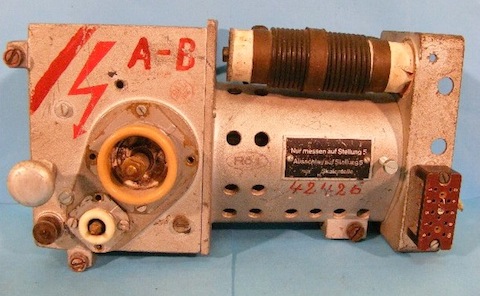
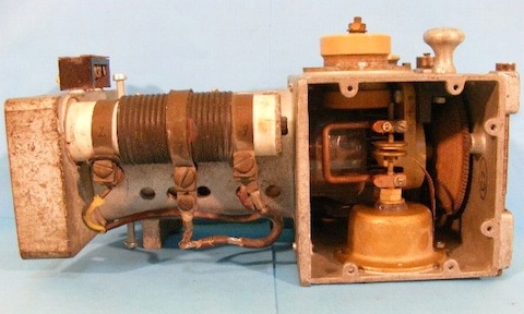
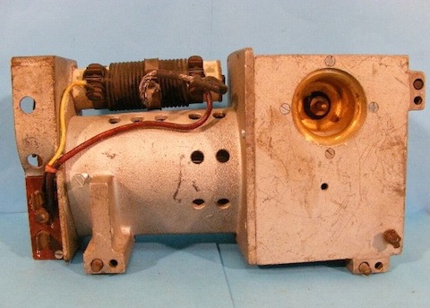
My TX Unit
My IF UNIT ZFV 62
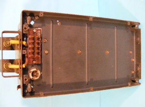

My ETHERODYNE
Bibliography
- TME 11-219 US report on German Radar, April 1945
- Arthur O. Bauer Web Site Foundation Center for German Communication and related Technologies
- Werner Muller : Ground Radar Systems of the Luftwaffe 1939-1945
- Wikipedia
- Arthur O. Bauer “Deckname Würzburg The technical history of the Würzburg radar system (1937 - 1945)”