History
The Telefunken Torn.E.b /24b-305 (Spez 976 Bs) receiver was a final product of Telefunken ‘portable’ receivers developed mainly for field use from the late 1920s onwards. They were intended for use both as a general purpose field receiver and as an accompanying receiver for a number of transmitters of the type normally found installed in signals trucks.
Designed on 1936 was produced, until the end of the war by Telefunken, Saba and Mende in about 200.000 units
Technology
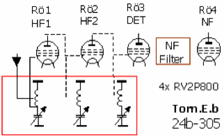
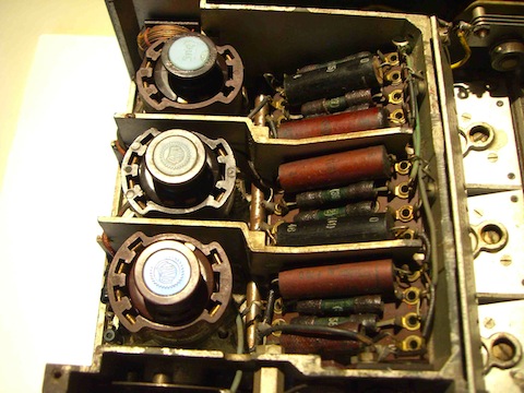
Torn.E.b employed the relatively new multipurpose pentode RV2 P800. These two volt filament valves could be used in a variety of configurations. The receiver had two RF stages, a regenerative detector stage and a low frequency or audio output stage. All stages used the same valve type very useful in the field as only one type of spare need be carried
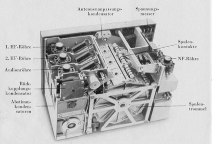
Telefunken engineers paid great attention to the mechanical aspects of the tuning systems and employed superbly made anti-backlash gearing.This ensured not only very fine adjustment of the reaction condenser but, in addition, the capability to return to the exact setting after changing back from another frequency band.
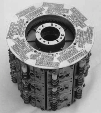
The coil turret is of cast alloy and contains completely screened compartments for each coil. The contacts are supported on cylindrical ceramic bars. The three gang tuning capacitor is also completely screened.
The Torn.E.b had been designed essentially as a CW receiver and a 900Hz filter (on the circuit diagram following the detector) could be brought in by activating the “Tonsieb” switch. General audio quality for speech and music, though acceptable, was not the primary requirement.
The frequency ranges covered by each bands are 100-6970 kHz in eight ranges : Band l -97 to 175kHz ; Band 2-172 to 310kHz ;Band 3- 306 to 552kHz ; Band 4- 541 to 977kHz ; Band 5-958 to 1720 kHz ;Band 6-1685 to 3030 kHz; Band 7-2940 to 4760 kHz ;Band 8- 4420 to 6970 kHz .
Torn E.b does not have a frequency scale but a calibration tables. For each range there are two calibration tables that are switched from the band selector drum A tuning dial has 100 divisions, which must be referred to the two calibration tables on over them is indicated the corresponding frequency every five divisions or degrees. For intermediate values is necessary taken into account the value indicated in a window in KHz. This indicates,, for each range chosen, the value of the degree at the tuning dial .
For example, place the drum on the range 7, where the tuning dial is in position 45, we can read at the calibration table 45 degree corresponds to the frequency 3760 KHz
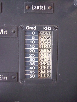
For know the frequency value corresponding to 47 degree, at the tuning dial, will be necessary a simple calculation. In the window above is written that at each grade correspond about 19 KHz (1 Grad = 19 KHz”), than at the closer value 45 = 3760 KHz we add the value of two degrees: 45 +2 = 47 than 19 KHz x 2 = 38 KHz . Then the frequency received is about 3786 KHz.
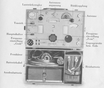
The power supplied by 2 VDC 800 ma for Heater=filaments (H) and 90 VDC 10 ma for Anodic (A)
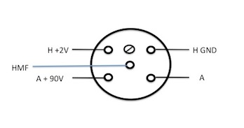
The HMF pin is used only with the transmitter.
Its construction remained unchanged until the end of the war except for minor changes mainly due to shortage of war strategic materials:
1) 1943: instrument for verify the batteries status was removed
2) 1944: zamak alloy frame instead of aluminum, with consequent increasing of weigh and fragility
Starting from a mid 1944 the receivers had all control console labels integrated with the front console plate, so it could be stamped in one manufacturing step. The inconvenience is the less readability of the indications.
The set is rather small, 36.5 cm wide, 24.5 cm high and 22 cm deep. This is for the receiver alone. Together with the battery and accessories 'Tornister" height is 46 cm. But the weight of the complete unit is surprising, 24 kg. The complete set consists of the receiver and the accessory case, 4000 ohm headphones, antenna and ground leads. In addition one of the three power sources must be used. The original dry cells are not made any more but any dry cell battery that produces 90 volts can be used. The receivers turn up very often, the accessory chests are rare items.
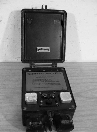
Under certain circumstances, in case of necessity, the receiver could work with a Power Supply vibrator Wechseirichter EW.b that starting form the filaments 2V battery transform it in 2 V pulses that by a transformer are elevate and than rectified in order to obtain the anodic 90 VDC.
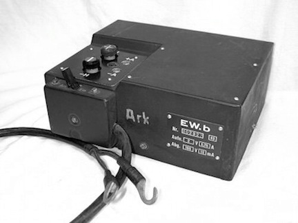
This power supply had the same size as the battery anode. A second type of power supply is named EW.c.. The power voltage of this inverter is provided from 12 VDC vehicle battery .
MY TORN EB
My Torn EB was produced in 1943. Is clearly visible form the picture that the voltmeter for read the filament (2V) and anodic voltage (90V) , on the top left, is missing. In fact on 1943, due to the shortage of war materials, this meter was eliminated and replaced by a coverl plate.
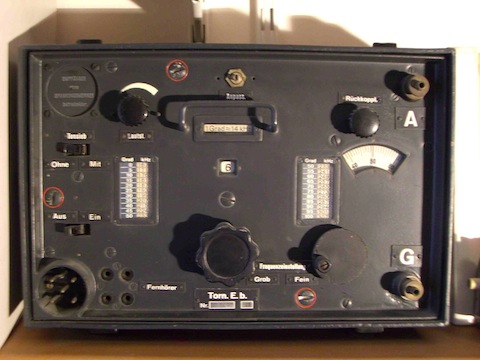
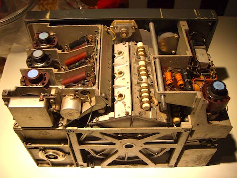
On the center rear view is clearly visible the rotating coil turret that can rotate in 8 positions.
In the following detail pictures are shown the four valves RV2P800
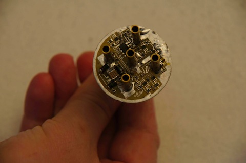
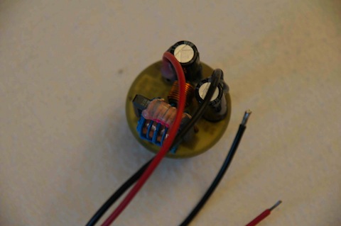
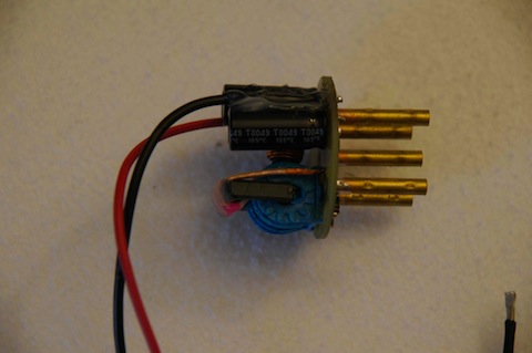
MODERN POWER SUPPLY
I have purchased some years ago a ultra compact modern switching power supply. in SMD technology (sorry no info about the seller available) .
Its dimensions are comparable with the original connector.
Bibliography
- Giovanni Longhi IN3LGH “Torn EB” CQ Elettronica magazine N° 128 June 1983
- R. T. Walker, G4PRI “The Torn.E.b The German Portable Battery Receiver Type 24b-305” Radio Bygones Magazine April/May 2003 Issue No. 82
- Technical Manual “Vorlauge Beschreibung und Bedienungsvorshrift des Tornister-Empfangers Torn. E.B./24b-305” Amsgabe April 1938