Top
E52a Koln “Blue” Restoration
Top
I will call this E52a Koln as “Blue” for distinguish it from the others in my collection
This radio was purchased on Ebay some years ago.
No informations was available about the internal status that the decision to purchase this radio was a real hazardous.
In the following picture the radio when arrives in my lab.
This radio was purchased on Ebay some years ago.
No informations was available about the internal status that the decision to purchase this radio was a real hazardous.
In the following picture the radio when arrives in my lab.
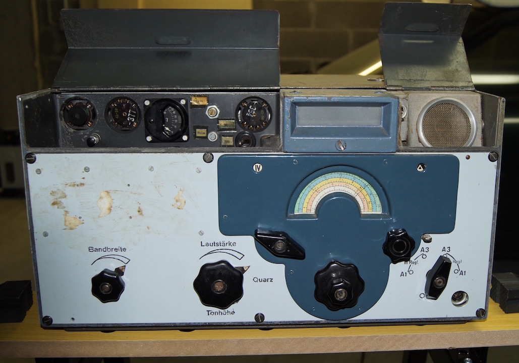
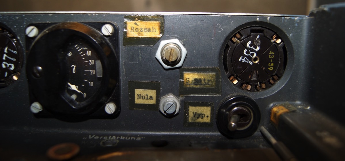
Some modifications were visually clearly evident.
- An integrated loudspeaker was applied on left side
- A headphone connector in a front panel
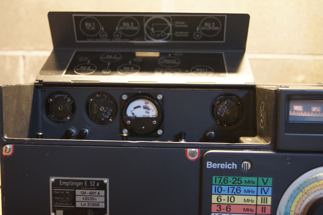
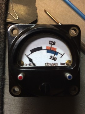
- The original tube tester instrument was replaced
- Additional trimmers and switch and switches on left side in Czech language
- Additional RX standby switch at the Power Supply unit
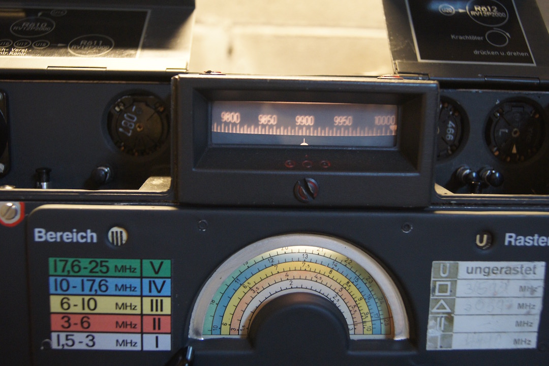
The tuning knob and band selector was very rough. This indicates that the radio was not used since a long time ago.
The first thing that I have done is to verify the electrical conditions without apply the 220AC, measuring the resistance at the tube pin was suggested in the Sengbusch book. With good results.
After that I have proceed to totally dismount the radio.
All the not original parts was removed and the circuit was restored according the original specifications
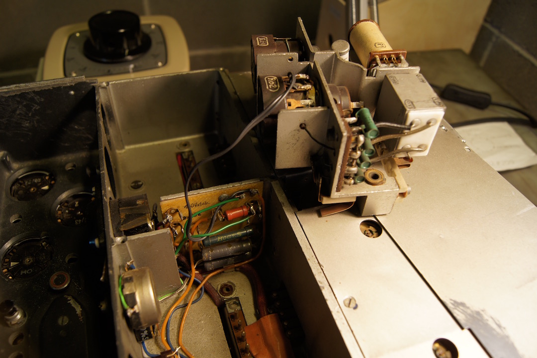
The missing BFO wiring at the demodulator unit has been implemented

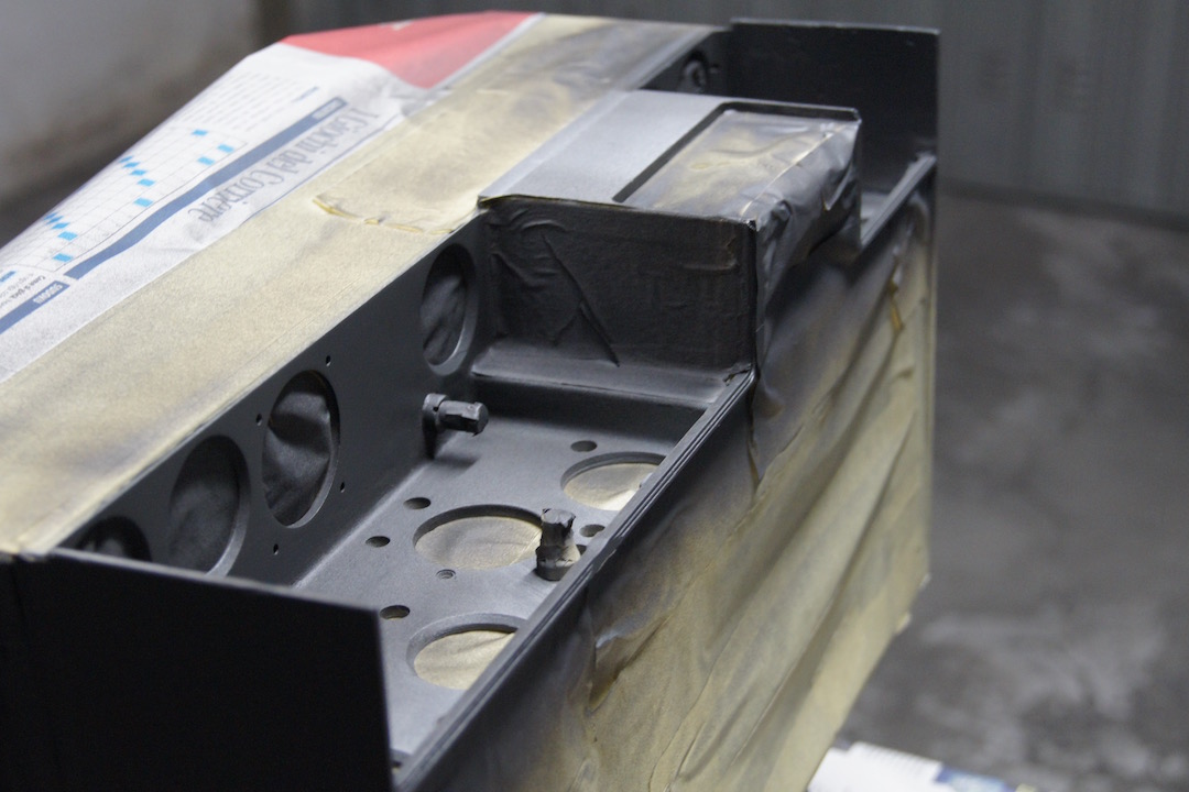
All the not original holes in the chassis has been patched using Bostick epoxy resin
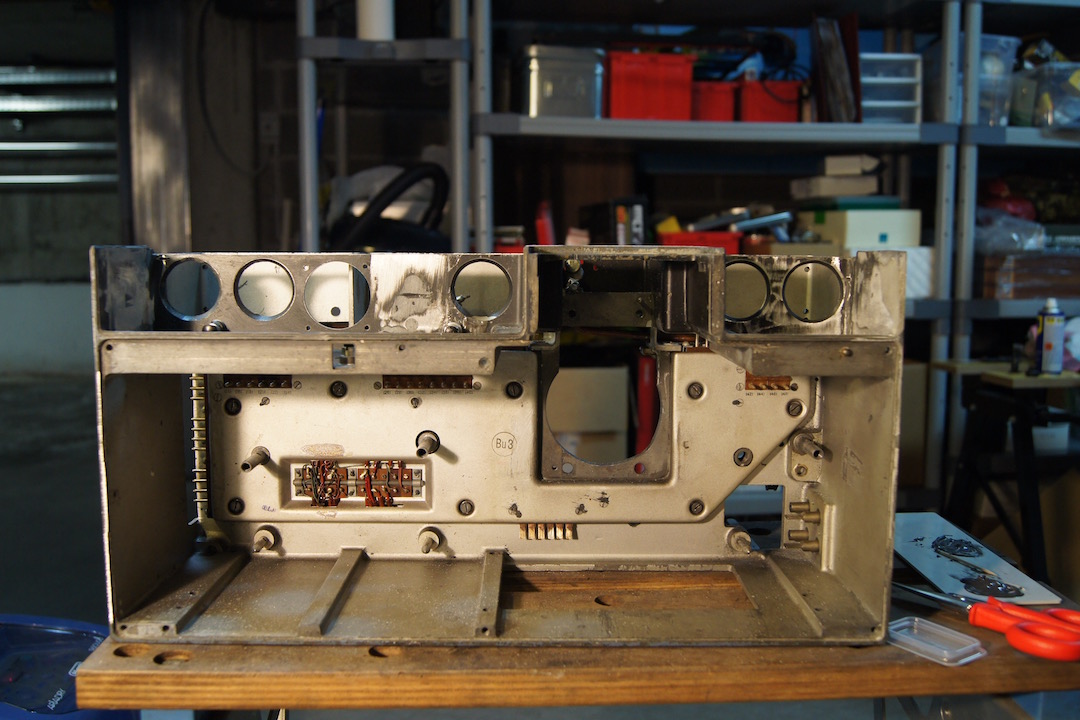
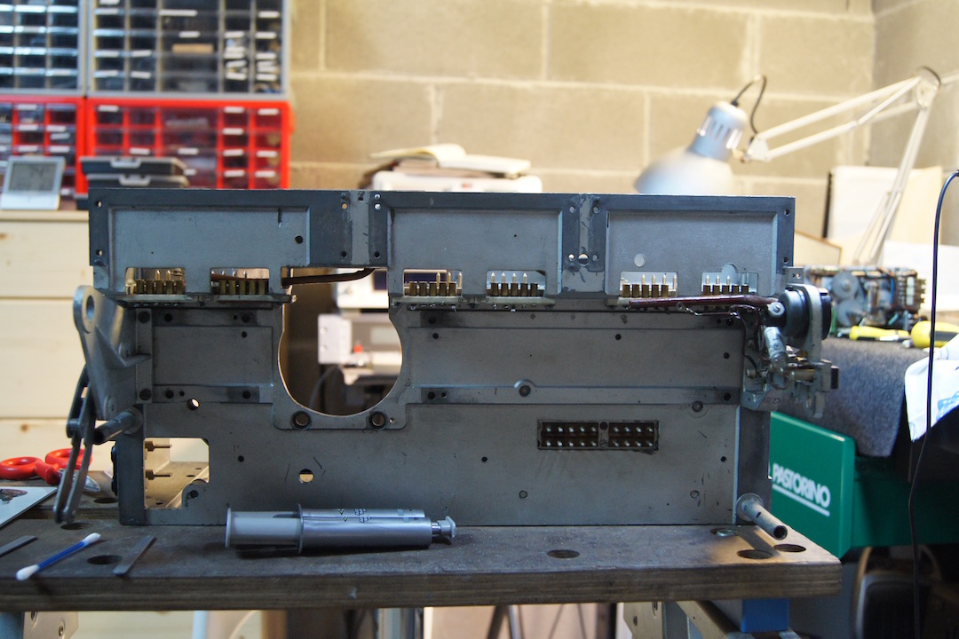
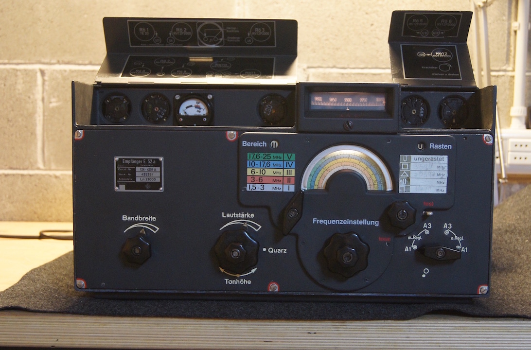
Than all has been repainted
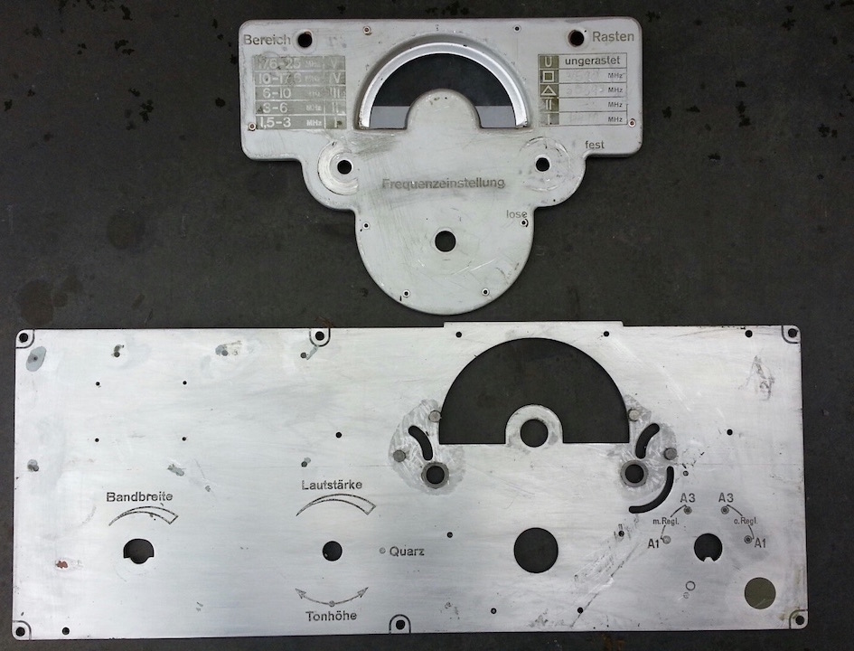
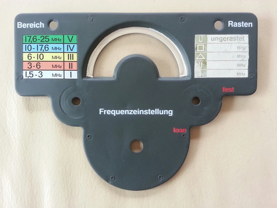
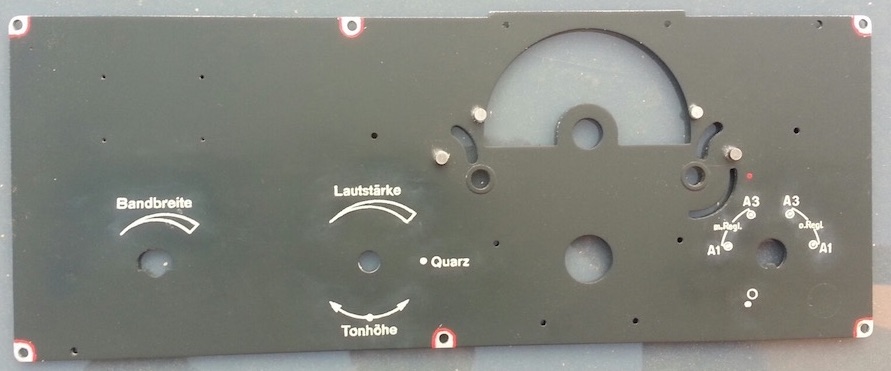
Also the front panel has been cleared and repainted
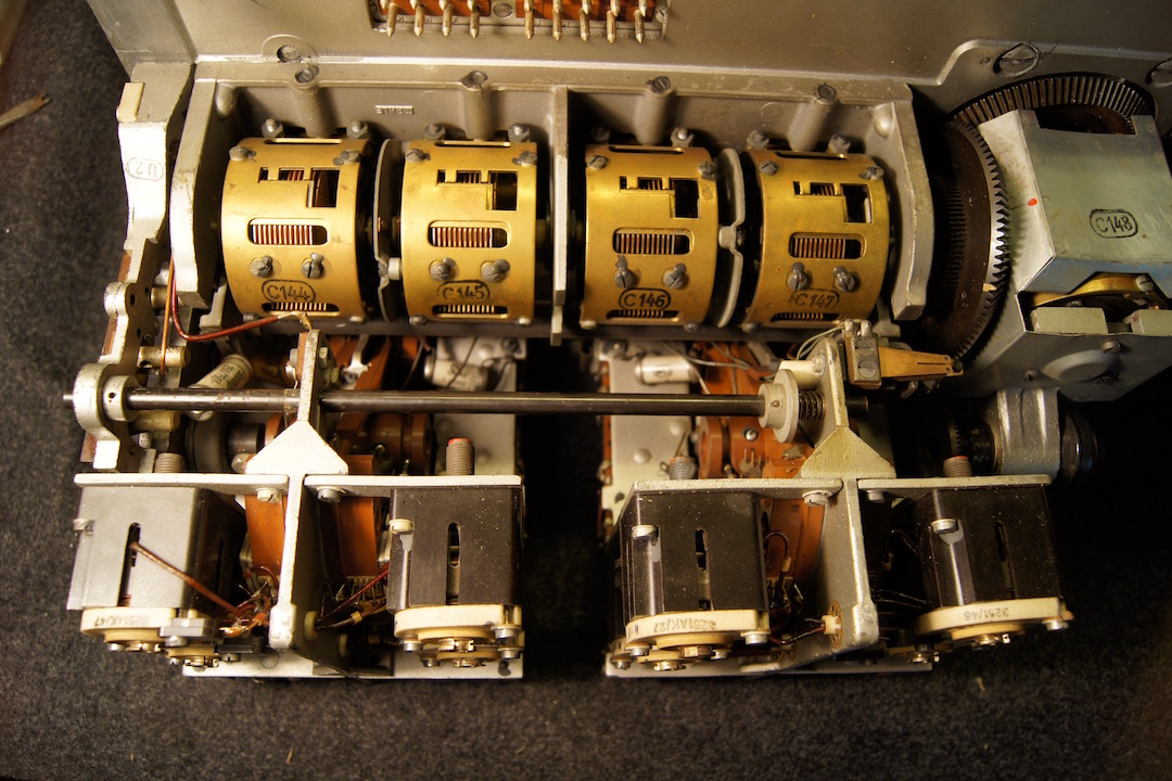
All the mechanical parts has been cleared with WD40, including the motorized tuning unit that was tested in stand alone mode.
After the remounting all the RF unit has been aligned and retuned
After the remounting all the RF unit has been aligned and retuned
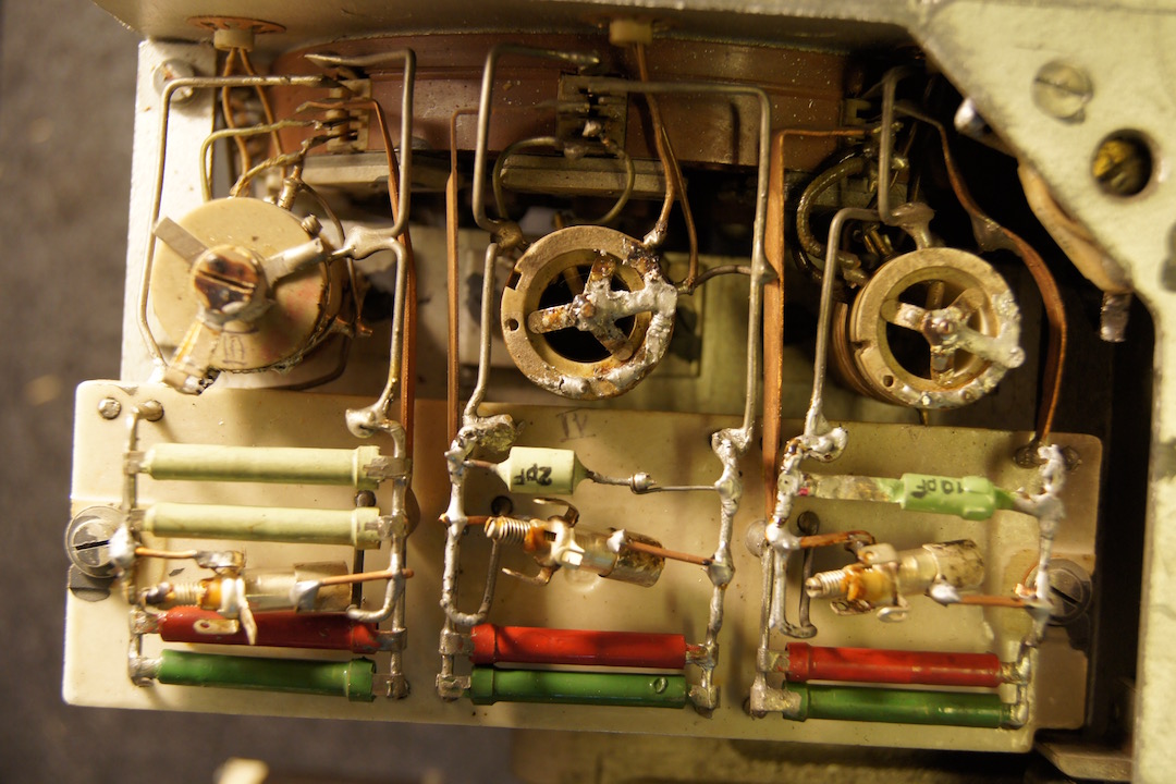
At the oscillator unit has been applied trimmers for the frequency scale LC alignment
The original instrument has been reproduced using another 100uA instrument. The original scale ahs been reproduced and the shunt resistor has been properly selected.
In the following table are summarized the average MDS [dBm] values and the the average frequency scale reading variations [KHz] measured after the final alignment
Band I II III IV V | MDS [dBm] -138 -139 -139 -137 -133 | Frequency Deviation [KHz] 2 1 4 3 6 |