Top
KAUTER CRYSTAL FILTERS
Top
In late 30s Telefunken Company further develops the crystal filters with variable bandwidth so as to come closer to the ideal. Their top receivers produced during WWII like E52 Koln E53 Ulm, T9K39 Main and T8L39 Wupper, employing two identical filters sections isolated from each other by a tube amplifier stage.
In the following picture is showed the E52 Koln IF crystal filter circuit
In the following picture is showed the E52 Koln IF crystal filter circuit
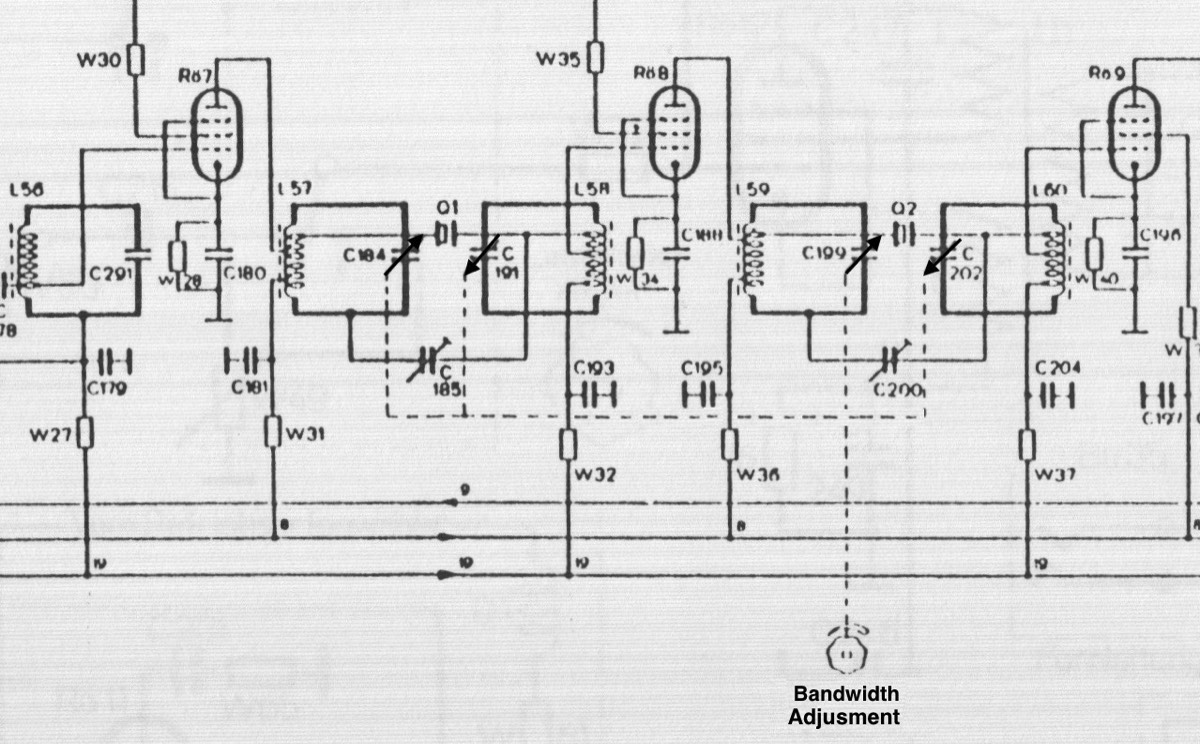
Figure 1 E52 Köln Crystal Filters Shematic
Each band-filter section used a mutual differential capacitor-tuning : Δ C up = Δ C down where Δ C up=C 184 & C 199 and Δ C down= C 191&C 202
C 185 and C 200 are the neutralization trimmers, which is to be adjusted individually, as to counter the parallel parasite capacity of the quartz crystal and its attached wiring.
According the E 52 Koln specification it could tune between: +/-200 Hz and +/-5 kHz bandwidth.
The groundwork for the design of these filters was laid by Wolfgang Kautter of the Telefunen labs in 1937.
In the following part of this page I will try to summarize the writings by Kautter for Telefunken Zeitung magazine Nr 77 in 1937 “Breite Quarzregelfilter” (“Broadband variable-bandwidth crystal filters”) Telefunken pages 42 – 50.
According the following original picture is considered a crystal filter controlled by two resonant circuit, similar to those used in the Koln receiver. It is assumed that the parallel capacitance Cq of the quartz is neutralized.
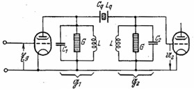
Figure 2 Kautter’s reference schematic
Where G take into account the tube internal resistance, the anode load and the internal resistance of resonance circuit. The internal resistance of crystal filter can be considered negligible. Taking reference to the previous E52 Koln schematics C 1=C 184 &C 199; L=L 57, L 59 & L 58, L 60.
C 185 & C 200 are the trimmers for neutralize Cq
The bandwidth can be controlled by the detuning the two resonant circuits symmetrically, but in opposite direction respect to the resonance frequency of the quartz, like Koln receivers, or by varying the coupling between the quartz filter and the resonant circuits, like the Lorenz Ln 21021 Schwabenland receivers.

Figure 3 Kautter’s Patent Schematic
In this second case, employed in Ln21021 Schwabenland receiver, is implemented an impedance transformer that symmetrically allows varying the coupling between the quartz filter and the resonant circuits .With the higher impedance coupling the quartz filter impedance is less damped by resonant circuits. This impedance increasing is determined by the square of the transformation ratio.
For narrow filters :bandwidth = b << d = damping of the resonant circuit, the two control modes are theoretically equivalent. This is not true for large band filters.
When the bandwidth is controlled by changing the coupling of the crystal are obtained of the curves represented in the following Figure 4
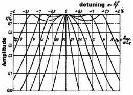
Figure 4 crystal filter Bandwidth control by various coupling
The level of the curve reaches the value equal to V0 (center band level) three times and then go down suddenly on the sides, if the damping of the quartz b0 exceed the damping of the resonant circuit d.
Stronger is the damping of the quartz much greater is the outward displacement of the peaks and greater is the curvature of the two inlets. With b0 «do the curve becomes as a filter with a single peak.
With b0«d the curve it is asymmetrical, also with low values of de-tuning, as shown in Figure 5
Stronger is the damping of the quartz much greater is the outward displacement of the peaks and greater is the curvature of the two inlets. With b0 «do the curve becomes as a filter with a single peak.
With b0«d the curve it is asymmetrical, also with low values of de-tuning, as shown in Figure 5

Figure 5
Than with b0«d the filter is completely not usable for our purpose. For Koln receiver has been selected a coupling factor b0/d=1 and then bo = d
The following Figure 6 shows the filter curve as a function of the symmetrically opposite detuning of resonant circuits.
The following Figure 6 shows the filter curve as a function of the symmetrically opposite detuning of resonant circuits.
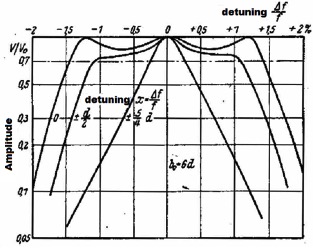
Figure 6 Detuning opposit-symmetrical of the two resonant circuits
In the following Figure 7, the bandwidth b is represented as a function of the obtained quartz damping b0. Both sizes are normalized with respect to the damping of the resonant circuit d

Figure 7 bandwidth in function of the crystal damping
In Figure 7 it is also represented the distance between the two peaks ym in function of the crystal damping b0 the distance between the two depressions is equal to ym / √3.
With the increase of the quartz damping the curve flexes a more. The following Figure 8 shows the flexing in function of the crystal damping.
With the increase of the quartz damping the curve flexes a more. The following Figure 8 shows the flexing in function of the crystal damping.
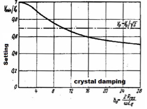
Figure 8
By combining Figure 7 and Figure 8 the following Figure 9 shows how changes the flexing in function of the bandwidth.
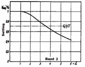
Figure 9
For Vmin / V0 = 1 / √2 the minimum sag point is for a band b = 3,5d.
With the increase of the resonant circuits damping increase the bandwidths that can be achieved, and the resonant resistance
Is possible to obtain large bandwidths only if the crystals have a very low inductance and therefore a very small intrinsic physical width.
In the second part of the Kautter article is illustrated the very complex mathematical study of these filter.
The resulting formula for the frequency response of Koln-type filter is the following:

The formula is obtained considering some simplification valid only for narrow bandwidth of < 10%
In the E52 Koln receiver witch employed an IF of 1 MHz the coupling factor is about 1.
The crystal inductance is around 1200uH whereas the LC values are about 160uH/160pF for the a maximum bandwidth.
The filter original E52 Koln IF specifications that consider the two crystal filters preceding 6 pole RC filters are : +/- 5kHz/-3dB to +/-13kHz/-60dB and +/-200Hz/-3dB to +/-2kHz/-60dB. (source Luftbooden Empfanger Programm original document)
The bandwidth specification of 26kHz at -60dB applies to the combination of the crystal filters and the preceding 6 pole LC filter. The -60db bandwidth of the crystal filter alone is between 32 to 35kHz
The specification of+/- 2kHz at -60db for the +/-200Hz bandwidth is an error because for the law of physics, bandwidth of only the crystal filter alone at -60dB cannot be smaller than about +/-6,4 KHz. We also know that neither the 6-pole LC pre-filter (because it is more than 15kHz wide) nor the terminating LC circuits add to the selectivity because they are symmetrically detuned by about 35khz on each side.
In the following the explanation :the shape factor for a single resonator can roughly be calculated by multiplying the 3db bandwidth with the attenuation factor. Example: 3db Bandwidth =200Hz, attenuation 1:32 (-30db) ---> 200Hz x 32 = 6,4kHz Because we have 2 independent sections, this leads to about 6,4kHz minimum Bandwidth at -60db. This is the theoretical (ideal) Bandwidth ratio which in practice cannot be achieved.
Even with bandwidth of about +/-100Hz at -3dB the following simulation of the E52 Koln crystal filter shows that practically the filter bandwidth cannot be lower than +/-4 KHz at -60dB
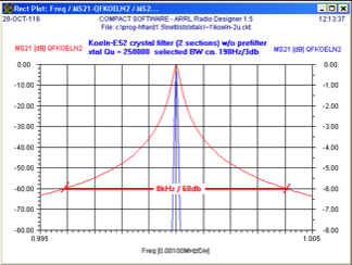
Figure 10
In the following picture is showed the L57 and L58 inductances with different taps.
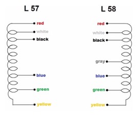
Different taps were selected during the calibration.
In the following table are indicated the values
In the following table are indicated the values
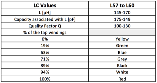
Table 1
If you take in reference the circuit in Figure 2 for calculate the equivalent crystal inductance to the top of LC circuits is necessary to take into account the squares of the turn ratio of L in Figure 1. For example if you choose the tap gray that in the Table 1 that match to 71% of the tap windings the equivalent crystal inductance at the top of the LC circuit will be 1300uH /(0,71 x 0,71)= about 2600uH
In the following picture is showed the simulation of the response curve related E52 Koln double crystal filter, at various setting of the continuously-variable bandwidth control.
In the following picture is showed the simulation of the response curve related E52 Koln double crystal filter, at various setting of the continuously-variable bandwidth control.
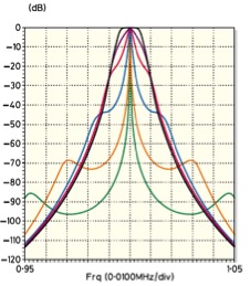
Figure 10 E52 Köln crystal filter response
The picture shows an undesirable effect, inherent with the bandwidth control, previously described trough the Kautter paper : in the intermediate setting towards narrower band-widths, the response curve immediately loses its nice flat-top and deteriorates into a relatively narrow peak response with very shallow slopes. Only the extreme bandwidth setting do the response very good. In order to mitigate this effect, and increase the total stop band rejection, in the E52 Koln receiver, the dual crystal filter is preceding by 6 pole LC filter, that together with the additional 2 pole band filter preceding the demodulator stage. With this configuration it assures the exceptional total stop band rejection of over 130 dB.
In the following picture is showed the E52 Koln filter with the additional mentioned 8 pole LC filters.
In the following picture is showed the E52 Koln filter with the additional mentioned 8 pole LC filters.

Figure 11 E52 Köln IF filter response
References
• W. Kautter “Breite Quartzregelfilter” („Broadband variable-bandwidth crystal filters“) Telefunken Zeiitung Nr 77 (1937) pages 42-50
• Horst Steder DJ6EV “The classic Quartz Single-Crystal Filter“ (2003)
• “The Koeln E52 Filter “ Radcom (January 2000) Technical Topics pages 56-57
• Arthur Bauer “Foundation for German communication and related technologies” web site
• Horst Steder DJ6EV “The classic Quartz Single-Crystal Filter“ (2003)
• “The Koeln E52 Filter “ Radcom (January 2000) Technical Topics pages 56-57
• Arthur Bauer “Foundation for German communication and related technologies” web site